Toyota Tacoma (2015-2018) Service Manual: Data List / Active Test
DATA LIST / ACTIVE TEST
1. DATA LIST
NOTICE:
In the table below, the values listed under "Normal Condition" are reference values. Do not depend solely on these reference values when deciding whether a part is faulty or not.
HINT:
Using the Techstream to read the Data List allows the values or states of switches, sensors, actuators and other items to be read without removing any parts. This non-intrusive inspection can be very useful because intermittent conditions or signals may be discovered before parts or wiring is disturbed. Reading the Data List information early in troubleshooting is one way to save diagnostic time.
(a) Connect the Techstream to the DLC3.
(b) Turn the engine switch on (IG).
(c) Turn the Techstream on.
(d) Enter the following menus: Body Electrical / Smart Key / Data List.
(e) Read the Data List according to the display on the Techstream.
Smart Key|
Tester Display |
Measurement Item/Range |
Normal Condition |
Diagnostic Note |
|---|---|---|---|
|
Ignition Switch*9 |
Engine switch status / ON or OFF |
ON: Engine switch on (IG) OFF: Engine switch off |
Use this Data List item to help determine the cause when all the smart key system/wireless functions do not operate. |
|
#Codes |
Number of trouble codes / Min: 0, Max: 255 |
Number of stored DTCs displayed |
- |
|
Immobilizer when IG-ON |
Engine immobiliser system status when engine switch on (IG) / SET or UNSET |
SET: Engine immobiliser system set (driver door open and closed with engine switch on (IG)) UNSET: Engine immobiliser system not set with engine switch on (IG) or engine immobiliser system unset for 40 times after engine immobiliser system set |
- |
|
Immobiliser*9 |
Engine immobiliser system status determined by certification ECU (smart key ECU assembly) / Set or Unset |
Set: Engine immobiliser system set (engine start prohibited) (engine switch off) Unset: Engine immobiliser system unset (engine start permitted) (engine switch on (ACC) or on (IG)) |
If "Set" is displayed, the engine start function is prohibited.
|
|
Master Key |
Whether master key ID code matches ID code registered in certification ECU (smart key ECU assembly) / Match or No Match |
Match: ID code of master key matches ID code registered in certification ECU (smart key ECU assembly) No Match: ID code of master key does not match ID code registered in certification ECU (smart key ECU assembly) |
- |
|
Sub Key |
Whether sub key ID code matches ID code registered in certification ECU (smart key ECU assembly) / Match or No Match |
Match: ID code of sub key matches ID code registered in certification ECU (smart key ECU assembly) No Match: ID code of sub key does not match ID code registered in certification ECU (smart key ECU assembly) |
- |
|
BCC Malfunction*1 |
BCC signal status of transponder chip / OK or NG |
OK: BCC signal normal NG: BCC signal malfunction (malfunction in code computation in key/certification ECU (smart key ECU assembly)) |
Problems may be caused by the following:
|
|
Abnormal Status*1 |
Transponder chip status signal / OK or NG |
OK: Transponder chip status signal normal NG: Transponder chip status signal malfunction (malfunction in code computation in key/certification ECU (smart key ECU assembly)) |
Problems may be caused by the following:
|
|
Different Encrypt Code*1 |
Code status between transponder chip and certification ECU (smart key ECU assembly) / OK or NG |
OK: Codes of transponder chip and certification ECU (smart key ECU assembly) match NG: Codes of transponder chip and certification ECU (smart key ECU assembly) do not match |
Problems may be caused by the following:
|
|
Different Serial Number*1 |
Vehicle serial number / OK or NG |
OK: Signal from transponder chip and vehicle serial number stored in the certification ECU (smart key ECU assembly) match NG: Signal from transponder chip and vehicle serial number stored in the certification ECU (smart key ECU assembly) do not match |
Problems may be caused by the following:
|
|
Frame Error |
State of data sent from key / OK or NG |
OK: No problem with data sent from key NG: Problem with data sent from key |
Problems may be caused by the following:
|
|
Response |
Key response to signal from certification ECU (smart key ECU assembly) / OK or NG |
OK: Key responds to signal from certification ECU (smart key ECU assembly) NG: Key does not respond to signal from certification ECU (smart key ECU assembly) |
Problems may be caused by the following:
|
|
Engine Start Condition*2 |
Engine start permission from certification ECU (smart key ECU assembly) / OK or NG |
OK: Engine start permitted by certification ECU (smart key ECU assembly) NG: Engine start prohibited by certification ECU (smart key ECU assembly) |
- |
|
ID-BOX Sleep Condition*9 |
Certification ECU (smart key ECU assembly) sleep mode status / Yes or No |
Yes: Certification ECU (smart key ECU assembly) sleep mode possible No: Certification ECU (smart key ECU assembly) sleep mode not possible |
- |
|
ID-BOX Start Condition*3 |
Certification ECU (smart key ECU assembly) status / Yes or No |
Yes: Wake-up signal sent by certification ECU (smart key ECU assembly) No: Wake-up signal not sent by certification ECU (smart key ECU assembly) |
- |
|
Engine Start Request*4, *9 |
Request to certification ECU (smart key ECU assembly) to permit ECM to start engine / OK or NG |
OK: Engine start permission request signal received by certification ECU (smart key ECU assembly) NG: Engine start permission request signal not received by certification ECU (smart key ECU assembly) |
If OK is not displayed, the immobiliser cannot be unset by the ECM. |
|
3bit Code Request |
3-bit code request condition / OK or NG |
OK: 3-bit code request condition signal received NG: 3-bit code request condition signal not received |
- |
|
L Code Check*5 |
L code verification result / OK or NG |
OK: L code verification result normal NG: L code verification result abnormal |
Problem may be caused by the following:
|
|
Unlock Request Receive*6, *9 |
Status of steering unlock command from certification ECU (smart key ECU assembly) / OK or NG |
OK: Certification ECU (smart key ECU assembly) sends steering unlock command (within 10 seconds of engine switch turned on (ACC) or on (IG), or of engine start operation performed) NG: Certification ECU (smart key ECU assembly) does not send steering unlock command (engine switch not turned on (ACC) or on (IG), and engine start operation not performed) |
If OK is not displayed even when the steering unlock conditions are met, the certification ECU (smart key ECU assembly) may be malfunctioning. |
|
Lock Request Receive*7, *9 |
Status of steering lock command from certification ECU (smart key ECU assembly) / OK or NG |
OK: Certification ECU (smart key ECU assembly) sends steering lock command (within 10 seconds of any door opened with shift lever in P and engine switch off) NG: Certification ECU (smart key ECU assembly) does not send steering lock command (no door opened with shift lever in P and engine switch off) |
If OK is not displayed even when the steering lock conditions are met, the certification ECU (smart key ECU assembly) may be malfunctioning. |
|
L Code Check (Past) |
L code verification result (past) / OK or NG(Past) |
OK: Verification confirmed (past) NG(Past): Verification not confirmed (past) |
- |
|
EFI Code Receive*8, *9 |
Certification information sent to certification ECU (smart key ECU assembly) from ECM when ECM receives engine start permission signal from certification ECU (smart key ECU assembly) / OK or NG |
OK: Signal from ECM to unset engine immobiliser received by certification ECU (smart key ECU assembly) NG: Signal from ECM to unset engine immobiliser not received by certification ECU (smart key ECU assembly) |
- |
|
EFI communication |
State of communication to unset immobiliser between certification ECU (smart key ECU assembly) and ECM / OK or NG |
OK: Communication to unset immobiliser has started between certification ECU (smart key ECU assembly) and ECM NG: Communication to unset immobiliser has not started between certification ECU (smart key ECU assembly) and ECM |
If this item displays "NG" even though the conditions to unset the immobiliser have been met and the Engine Start Request Data List item displays "OK", the ECM may be malfunctioning. When the engine cannot be started, use this Data List item during troubleshooting. |
HINT:
- *1: This indicates that there is a problem with the communication format between the key and certification ECU (smart key ECU assembly). Wave interference, key or certification ECU (smart key ECU assembly) malfunctions, the key of another vehicle being used, etc. are possible causes.
- *2: Engine start is permitted when it is confirmed that the steering is unlocked and there are no malfunctions in the steering lock system. If engine start is not permitted, a steering lock ECU (steering lock actuator or upr bracket assembly) malfunction (relay, driver, etc.), an IGE circuit malfunction (harness or connector, certification ECU (smart key ECU assembly)), or a steering lock sensor malfunction are possible causes.
- *3: This indicates that transmission of the wake-up signal is possible ("Yes" indicates that the signal to begin verification-related LIN communication is being sent). When the steering lock motor is operating and an IGE ON signal is received (there is a steering lock operation request), or when communication is being performed between the certification ECU (smart key ECU assembly) and ECM, the display changes to "Yes".
- *4: This indicates that the engine start permission request signal (EGST) output from the ECM is being received by the certification ECU (smart key ECU assembly).
- *5: This indicates the certification results of the certification codes
of the steering lock ECU (steering lock actuator or upr bracket assembly)
and certification ECU (smart key ECU assembly).
When the steering lock ECU (steering lock actuator or upr bracket assembly) receives an unlock request from the certification ECU (smart key ECU assembly), confirmation of the certification ECU (smart key ECU assembly) L code is performed. If the L code matches, the steering lock ECU (steering lock actuator or upr bracket assembly) unlocks the steering.
- *6: The certification ECU (smart key ECU assembly) outputs a steering lock unlock request for 10 seconds after the engine switch is turned on (ACC) or on (IG), or an engine start operation is performed.
- *7: The certification ECU (smart key ECU assembly) outputs a steering lock lock request for 10 seconds after the engine switch is turned off and any door is opened with the shift lever in P.
- *8: This indicates that the certification ECU (smart key ECU assembly) is receiving verification information from the ECM. If the ECM can send the information, the display changes to "OK".
- *9: Please refer to the following Data List of the actual vehicle.
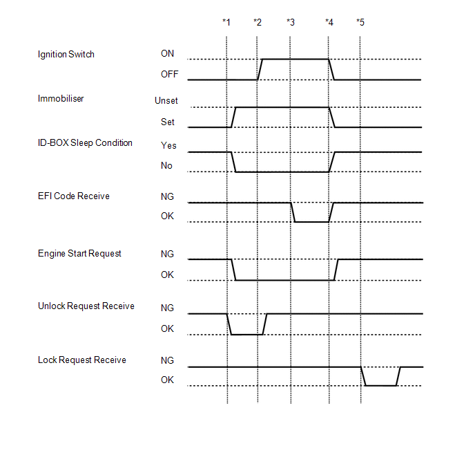
With the engine switch off and the shift lever in P, perform the following procedures and check the power source mode.
- *1: Without depressing the brake pedal, press the engine switch and check that the power source mode turns on (ACC).
- *2: Without depressing the brake pedal, press the engine switch and check that the power source mode turns on (IG).
- *3: While depressing the brake pedal, press the engine switch and check that the engine starts.
- *4: Press the engine switch and check that the power source mode turns off.
- *5: Door is opened (steering lock operation starts when door is opened).
(f) Enter the following menus: Powertrain / Engine / Data List.
(g) Read the Data List according to the display on the Techstream.
Engine|
Tester Display |
Measurement Item/Range |
Normal Condition |
Diagnostic Note |
|---|---|---|---|
|
Immobiliser Fuel Cut |
Status of immobiliser fuel cut / ON or OFF |
- |
- |
2. ACTIVE TEST
HINT:
Using the Techstream to perform Active Tests allows relays, VSVs, actuators and other items to be operated without removing any parts. This non-intrusive functional inspection can be very useful because intermittent operation may be discovered before parts or wiring is disturbed. Performing Active Tests early in troubleshooting is one way to save diagnostic time. Data List information can be displayed while performing Active Tests.
(a) Connect the Techstream to the DLC3.
(b) Turn the engine switch on (IG).
(c) Turn the Techstream on.
(d) Enter the following menus: Body Electrical / Smart Key / Active Test.
(e) According to the display on the Techstream, perform the Active Test.
Smart Key|
Tester Display |
Test Part |
Control Range |
Diagnostic Note |
|---|---|---|---|
|
Immobiliser Indicator |
Security indicator light |
OFF/ON |
- |
 Terminals Of Ecu
TERMINALS OF ECU
1. CHECK ENGINE SWITCH
(a) Measure the resistance and voltage according to the value(s) in the table
below.
Terminal No. (Symbol)
Input/Output
...
 Diagnostic Trouble Code Chart
DIAGNOSTIC TROUBLE CODE CHART
HINT:
If a trouble code is output during the DTC check, inspect the trouble areas listed
for that code. For details of the code, refer to the "See page" bel ...
Other materials:
Diagnosis System
DIAGNOSIS SYSTEM
DIAGNOSIS FUNCTION
(a) The diagnosis function turns off the cruise control indicator, illuminates
the master warning light and displays a warning message when a malfunction is detected.
When a malfunction is detected in the dynamic radar cruise control system, DTCs
are store ...
Diagnostic Trouble Code Chart
DIAGNOSTIC TROUBLE CODE CHART
Smart Key System
DTC Code
Detection Item
See page
B27A1
Open in Driver Side Electrical Antenna Circuit
B27A5
Open in Front Floor Electrical Key Oscillator Circuit
...
Inspection
INSPECTION
PROCEDURE
1. INSPECT CLUTCH DISC ASSEMBLY
NOTICE:
When replacing the clutch disc assembly, make sure to perform an inspection of
the flywheel sub-assembly and clutch cover assembly.
(a) Using a vernier caliper, measure the rivet depth.
Minimum rivet depth:
0.3 mm ...
