
Toyota Tacoma (2015-2018) Service Manual: Removal
REMOVAL
CAUTION / NOTICE / HINT
CAUTION:
- Some of these service operations affect the SRS airbag system. Read
the precautionary notices concerning the SRS airbag system before servicing
(See page
.gif) ).
). - If the side airbag was deployed, replace the front seat assembly with a new one.
PROCEDURE
1. PRECAUTION
NOTICE:
After turning the ignition switch off, waiting time may be required before disconnecting the cable from the negative (-) battery terminal. Therefore, make sure to read the disconnecting the cable from the negative (-) battery terminal notices before proceeding with work.
Click here
2. REMOVE CABLE FROM NEGATIVE BATTERY TERMINAL
CAUTION:
Wait at least 90 seconds after disconnecting the cable from the negative (-) battery terminal to disable the SRS system.
NOTICE:
When disconnecting the cable, some systems need to be initialized after the cable is reconnected.
Click here
3. REMOVE SEAT TRACK COVER
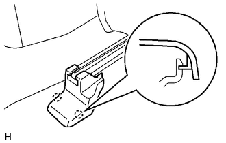
HINT:
Use the same procedures for both sides.
(a) Disengage the 2 claws to remove the seat track cover.
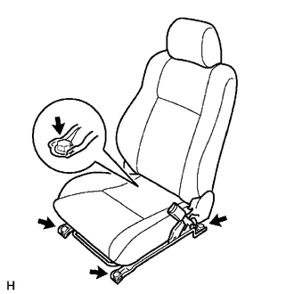
4. REMOVE FRONT SEAT ASSEMBLY
(a) Disengage the wire harness clamp.
(b) Disconnect the connectors.
(c) Disconnect the front seat airbag connector.
(1) Place a finger on the slider, slide the slider to release the lock, and then disconnect the front seat airbag connector.
.png) Text in Illustration
Text in Illustration
|
*1 |
Slider |
- |
- |
|
*a |
Push |
*b |
Slide |
(d) Move the seat to the center position.
|
(e) Remove the 4 bolts and front seat assembly. NOTICE: Be careful not to damage the vehicle body. |
|
 Installation
INSTALLATION
CAUTION / NOTICE / HINT
CAUTION:
Some of these service operations affect the SRS airbag system. Read
the precautionary notices concerning the SRS airbag system before servi ...

Other materials:
Adjustment
ADJUSTMENT
CAUTION / NOTICE / HINT
HINT:
Use the same procedures for both the LH and RH sides.
The procedure described below is for the LH side.
Centering bolts are used to mount the door hinge to the vehicle body
and door. The door cannot be adjusted with the centering bolts ...
Short to GND in Immobiliser System Power Source Circuit (B278A)
DESCRIPTION
When there is a short to GND in the power supply for the transponder key amplifier
of the engine switch, the certification ECU (smart key ECU assembly) stores this
DTC.
DTC Code
DTC Detection Condition
Trouble Area
DTC Output Confirmation ...
Motor Power Supply Voltage Circuit (C142B-C146D)
DESCRIPTION
The motor relay and motor fail-safe relay are built into the brake actuator assembly.
During ABS, TRAC, VSC, or brake assist operation, the skid control ECU (brake
actuator assembly) turns on the motor relay to run the pump motor in the brake actuator
assembly.
When a motor system ...
