Toyota Tacoma (2015-2018) Service Manual: Removal
REMOVAL
PROCEDURE
1. REMOVE SPIRAL CABLE WITH SENSOR SUB-ASSEMBLY
(See page .gif) )
)
2. REMOVE WINDSHIELD WIPER SWITCH ASSEMBLY
3. REMOVE HEADLIGHT DIMMER SWITCH ASSEMBLY
|
(a) Disconnect the connector. |
|
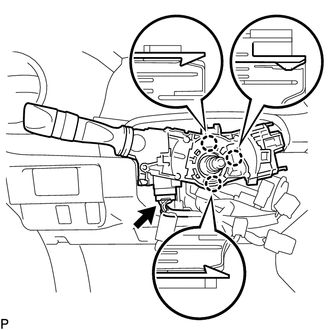
(b) Disengage the 3 claws to remove the headlight dimmer switch assembly.
 Components
COMPONENTS
ILLUSTRATION
...
 Inspection
INSPECTION
PROCEDURE
1. INSPECT HEADLIGHT DIMMER SWITCH ASSEMBLY
(a) Check the resistance.
(1) Measure the resistance according to the value(s) in the table below.
Text in Illustrati ...
Other materials:
High Power Supply Voltage Malfunction (C1417)
DESCRIPTION
If a malfunction is detected in the power supply circuit, the skid control ECU
(housed in the master cylinder solenoid) stores this DTC and the fail-safe function
prohibits ABS/VSC/TRAC operation.
This DTC is stored when the IG1 terminal voltage deviates from the DTC detection
co ...
Fuel Main Valve
Components
COMPONENTS
ILLUSTRATION
Removal
REMOVAL
PROCEDURE
1. REMOVE FUEL SUCTION TUBE WITH PUMP AND GAUGE ASSEMBLY
(See page )
2. REMOVE FUEL SENDER GAUGE ASSEMBLY
3. REMOVE NO. 1 FUEL SUB-TANK
4. REMOVE FUEL PUMP FILTER
5. REMOVE FUEL MAIN VALVE ASSEMBLY
(a) Remove t ...
Terminals Of Ecu
TERMINALS OF ECU
1. CLEARANCE WARNING ECU ASSEMBLY
(a) Disconnect the C30 connector from the clearance warning ECU assembly.
(b) Measure the voltage and resistance according to the value(s) in the table
below.
Terminal No. (Symbol)
Wiring Color
Terminal Descr ...
