Toyota Tacoma (2015-2018) Service Manual: Removal
REMOVAL
PROCEDURE
1. REMOVE AIR CONDITIONING CONTROL ASSEMBLY (for Automatic Air Conditioning System)
(See page .gif) )
)
2. REMOVE INTEGRATION PANEL SUB-ASSEMBLY (for Manual Cooler System)
(See page )
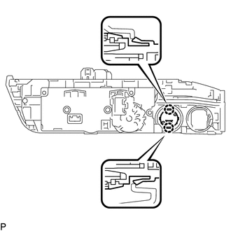
3. REMOVE TRANSFER POSITION SWITCH
|
(a) Detach the 2 claws to remove the transfer position switch. |
|
 On-vehicle Inspection
ON-VEHICLE INSPECTION
PROCEDURE
1. INSPECT INDICATOR LIGHT
(a) Inspect the 4HI Indicator Light:
(1) Start the engine.
(2) Change the 4WD control switch from 2WD to 4H.
(3) Check the 4HI indicato ...
 Installation
INSTALLATION
PROCEDURE
1. INSTALL TRANSFER POSITION SWITCH
(a) Attach the 2 claws to install the transfer position switch.
2. INSTALL AIR CONDITIONING CONTROL ASSEMBLY (for Automatic Air Condition ...
Other materials:
Data List / Active Test
DATA LIST / ACTIVE TEST
1. READ DATA LIST
HINT:
Using the Techstream to read the Data List allows the values or states of switches,
sensors, actuators and other items to be read without removing any parts. This non-intrusive
inspection can be very useful because intermittent conditions or sig ...
High Beam Headlight Circuit
DESCRIPTION
The main body ECU (multiplex network body ECU) controls the high beam headlights.
WIRING DIAGRAM
CAUTION / NOTICE / HINT
NOTICE:
Inspect the fuses for circuits related to this system before performing
the following inspection procedure.
If the main body ECU (multip ...
Customize Parameters
CUSTOMIZE PARAMETERS
PROCEDURE
1. CUSTOMIZE WIRELESS DOOR LOCK CONTROL SYSTEM
HINT:
The following items can be customized.
NOTICE:
When the customer requests a change in a function, first make sure that
the function can be customized.
Be sure to make a note of the current setti ...
