Toyota Tacoma (2015-2018) Service Manual: Rear Sensor Communication Malfunction (C1AED)
DESCRIPTION
This DTC is stored when there is an open or short circuit in the communication line between the rear sensors and the ECU, or when there is a malfunction in a rear sensor.
|
DTC No. |
DTC Detection Condition |
Trouble Area |
|---|---|---|
|
C1AED |
An open or short circuit in the communication line between the rear sensors and ECU or a malfunction in a rear sensor during initialization mode after the ignition switch is turned ON. |
|
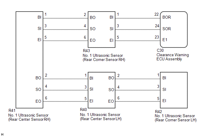
WIRING DIAGRAM
PROCEDURE
|
1. |
CHECK DTC OUTPUT (C1AED) |
(a) Check for DTCs (See page .gif) ).
).
(b) Clear the DTCs (See page ).
(c) Recheck for DTCs (See page ).
|
Result |
Proceed to |
|---|---|
|
DTC C1AED is output |
A |
|
No DTCs are output |
B |
| B | .gif) |
USE SIMULATION METHOD TO CHECK |
|
.gif)
|
2. |
CHECK HARNESS AND CONNECTOR (CLEARANCE WARNING ECU ASSEMBLY - REAR CORNER SENSOR RH) |
(a) Disconnect the C30 connector from the clearance warning ECU assembly.
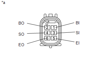
(b) Disconnect the R43 connector from the No. 1 ultrasonic sensor.
(c) Measure the resistance according to the value(s) in the table below.
Standard Resistance:
|
Tester Connection |
Condition |
Specified Condition |
|---|---|---|
|
C30-22 (BOR) - R43-1 (BI) |
Always |
Below 1 Ω |
|
C30-24 (SOR) - R43-3 (SI) |
||
|
C30-23 (E1) - R43-5 (EI) |
||
|
C30-22 (BOR) - Body ground |
10 kΩ or higher |
|
|
C30-24 (SOR) - Body ground |
||
|
C30-23 (E1) - Body ground |
| NG | |
REPAIR OR REPLACE HARNESS OR CONNECTOR |
|
|
3. |
CHECK HARNESS AND CONNECTOR (REAR CORNER SENSOR RH - REAR CENTER SENSOR RH) |
(a) Disconnect the R43 and R41 connectors from the No. 1 ultrasonic sensors.
(b) Measure the resistance according to the value(s) in the table below.
Standard Resistance:
|
Tester Connection |
Condition |
Specified Condition |
|---|---|---|
|
R43-2 (BO) - R41-1 (BI) |
Always |
Below 1 Ω |
|
R43-4 (SO) - R41-3 (SI) |
||
|
R43-6 (EO) - R41-5 (EI) |
||
|
R43-2 (BO) - Body ground |
10 kΩ or higher |
|
|
R43-4 (SO) - Body ground |
||
|
R43-6 (EO) - Body ground |
| NG | |
REPAIR OR REPLACE HARNESS OR CONNECTOR |
|
|
4. |
CHECK HARNESS AND CONNECTOR (REAR CENTER SENSOR RH - REAR CENTER SENSOR LH) |
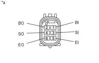
(a) Disconnect the R41 and R40 connectors from the No. 1 ultrasonic sensors.
(b) Measure the resistance according to the value(s) in the table below.
Standard Resistance:
|
Tester Connection |
Condition |
Specified Condition |
|---|---|---|
|
R41-2 (BO) - R40-1 (BI) |
Always |
Below 1 Ω |
|
R41-4 (SO) - R40-3 (SI) |
||
|
R41-6 (EO) - R40-5 (EI) |
||
|
R41-2 (BO) - Body ground |
10 kΩ or higher |
|
|
R41-4 (SO) - Body ground |
||
|
R41-6 (EO) - Body ground |
| NG | |
REPAIR OR REPLACE HARNESS OR CONNECTOR |
|
|
5. |
CHECK HARNESS AND CONNECTOR (REAR CENTER SENSOR LH - REAR CORNER SENSOR LH) |
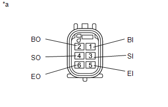
(a) Disconnect the R40 and R42 connectors from the No. 1 ultrasonic sensors.
(b) Measure the resistance according to the value(s) in the table below.
Standard Resistance:
|
Tester Connection |
Condition |
Specified Condition |
|---|---|---|
|
R40-2 (BO) - R42-1 (BI) |
Always |
Below 1 Ω |
|
R40-4 (SO) - R42-3 (SI) |
||
|
R40-6 (EO) - R42-5 (EI) |
||
|
R40-2 (BO) - Body ground |
10 kΩ or higher |
|
|
R40-4 (SO) - Body ground |
||
|
R40-6 (EO) - Body ground |
| NG | |
REPAIR OR REPLACE HARNESS OR CONNECTOR |
|
|
6. |
INSPECT NO. 1 ULTRASONIC SENSOR (REAR CORNER SENSOR RH) |
(a) Remove the No. 1 ultrasonic sensor (rear corner sensor RH) (See page
).
|
(b) Measure the resistance according to the value(s) in the table below. Standard Resistance:
|
|
| NG | |
REPLACE NO. 1 ULTRASONIC SENSOR (REAR CORNER SENSOR RH) |
|
|
7. |
INSPECT NO. 1 ULTRASONIC SENSOR (REAR CENTER SENSOR RH) |
(a) Remove the No. 1 ultrasonic sensor (rear center sensor RH) (See page
).
|
(b) Measure the resistance according to the value(s) in the table below. Standard Resistance:
|
|
| NG | |
REPLACE NO. 1 ULTRASONIC SENSOR (REAR CENTER SENSOR RH) |
|
|
8. |
INSPECT NO. 1 ULTRASONIC SENSOR (REAR CENTER SENSOR LH) |
(a) Remove the No. 1 ultrasonic sensor (rear center sensor LH) (See page
).
|
(b) Measure the resistance according to the value(s) in the table below. Standard Resistance:
|
|
| NG | |
REPLACE NO. 1 ULTRASONIC SENSOR (REAR CENTER SENSOR LH) |
|
|
9. |
REPLACE NO. 1 ULTRASONIC SENSOR (REAR CORNER SENSOR RH) |
|
|
10. |
CHECK DTC OUTPUT (C1AED) |
(a) Clear the DTCs (See page ).
(b) Check for DTCs (See page ).
|
Result |
Proceed to |
|---|---|
|
DTC C1AED is output |
A |
|
No DTCs are output |
B |
| B | |
END (REAR CORNER SENSOR RH WAS DEFECTIVE) |
|
|
11. |
REPLACE NO. 1 ULTRASONIC SENSOR (REAR CENTER SENSOR RH) |
|
|
12. |
CHECK DTC OUTPUT (C1AED) |
(a) Clear the DTCs (See page ).
(b) Check for DTCs (See page ).
|
Result |
Proceed to |
|---|---|
|
DTC C1AED is output |
A |
|
No DTCs are output |
B |
| B | |
END (REAR CENTER SENSOR RH WAS DEFECTIVE) |
|
|
13. |
REPLACE NO. 1 ULTRASONIC SENSOR (REAR CENTER SENSOR LH) |
|
|
14. |
CHECK DTC OUTPUT (C1AED) |
(a) Clear the DTCs (See page ).
(b) Check for DTCs (See page ).
|
Result |
Proceed to |
|---|---|
|
DTC C1AED is output |
A |
|
No DTCs are output |
B |
| B | |
END (REAR CENTER SENSOR LH WAS DEFECTIVE) |
|
|
15. |
REPLACE NO. 1 ULTRASONIC SENSOR (REAR CORNER SENSOR LH) |
|
|
16. |
CHECK DTC OUTPUT (C1AED) |
(a) Clear the DTCs (See page ).
(b) Check for DTCs (See page ).
|
Result |
Proceed to |
|---|---|
|
DTC C1AED is output |
A |
|
No DTCs are output |
B |
| A | |
REPLACE CLEARANCE WARNING ECU ASSEMBLY |
| B | |
END (REAR CORNER SENSOR LH WAS DEFECTIVE) |
 Rear Left Sensor Malfunction (C1AE6)
DESCRIPTION
The No. 1 ultrasonic sensor (rear corner sensor LH) is installed on the rear
bumper. The ECU detects obstacles based on signals received from the No. 1 ultrasonic
sensor (rear corner ...
 Rear Left Center Sensor Malfunction (C1AE7)
DESCRIPTION
The No. 1 ultrasonic sensor (rear center sensor LH) is installed on the rear
bumper. The ECU detects obstacles based on signals received from the No. 1 ultrasonic
sensor (rear center ...
Other materials:
Removal
REMOVAL
CAUTION / NOTICE / HINT
NOTICE:
If one of the camshaft timing gear bolts is already removed, do not remove any
other camshaft timing gear bolts.
PROCEDURE
1. REMOVE NO. 2 ENGINE UNDER COVER SUB-ASSEMBLY (w/ Off Road Package)
2. REMOVE NO. 1 ENGINE UNDER COVER SUB-ASSEMBLY
3. REMOVE ...
Data List / Active Test
DATA LIST / ACTIVE TEST
1. DATA LIST
HINT:
Using the Techstream to read the Data List allows the values or states of switches,
sensors, actuators and other items to be read without removing any parts. This non-intrusive
inspection can be very useful because intermittent conditions or signals ...
System Description
SYSTEM DESCRIPTION
1. DESCRIPTION
A part-time 2-speed VF2CM transfer uses a touch select 2-4 and high-low
system, enabling the driver to switch between 2WD, H4 and L4 modes by turning
the transfer position switch.
Through these switch signals, the 4 wheel drive control ECU actua ...
