Toyota Tacoma (2015-2018) Service Manual: Rear Console Box
Components
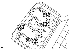
COMPONENTS
ILLUSTRATION
ILLUSTRATION
Installation
INSTALLATION
PROCEDURE
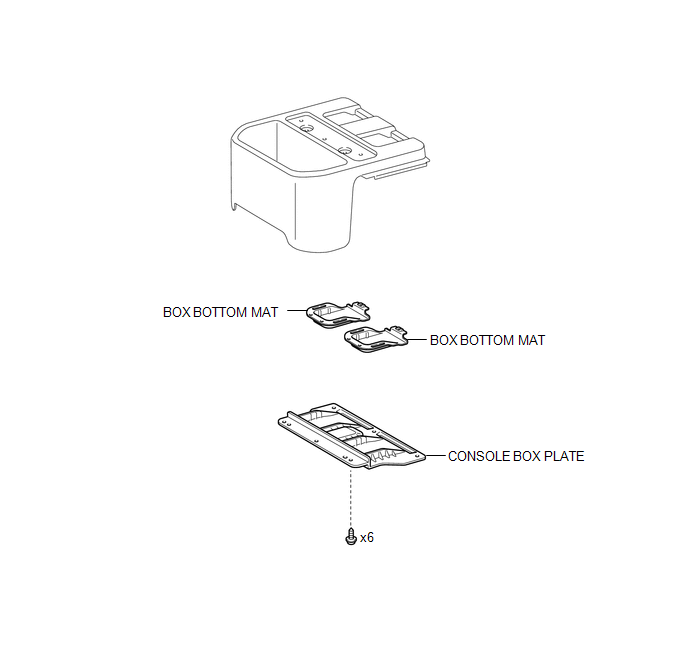
1. INSTALL BOX BOTTOM MAT
(a) Engage the 10 guides and install the 2 box bottom mats.
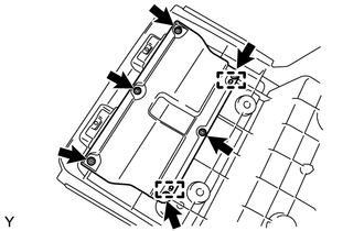
2. INSTALL CONSOLE BOX PLATE
(a) Engage the 2 guides and install the console box plate.
(b) Install the 6 screws.
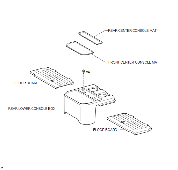
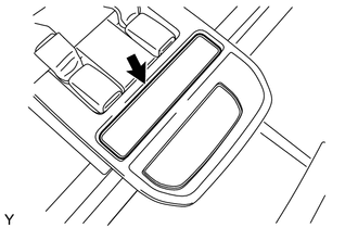
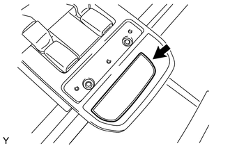
3. INSTALL REAR LOWER CONSOLE BOX
(a) Engage the 2 guides and install the lower console box.
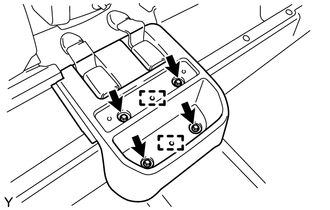
(b) Install the 4 bolts.
4. INSTALL FRONT CENTER CONSOLE MAT
(a) Install the front center console mat.
5. INSTALL REAR CENTER CONSOLE MAT
(a) Install the rear center console mat.
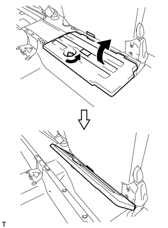
6. INSTALL FLOOR BOARD
|
(a) Return the floor board and engage the lock. HINT: Use the same procedure for both sides. |
|
Removal
REMOVAL
PROCEDURE
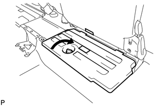
1. REMOVE FLOOR BOARD
|
(a) Release the lock and fasten the floor board to the seat bottom. HINT: Use the same procedure for both sides. |
|
2. REMOVE REAR CENTER CONSOLE MAT
|
(a) Remove the front center console mat. |
|
3. REMOVE FRONT CENTER CONSOLE MAT
|
(a) Remove the rear center console mat. |
|
4. REMOVE REAR LOWER CONSOLE BOX
|
(a) Remove the 4 bolts. |
|
(b) Disengage the 2 guides and remove the lower console box.
5. REMOVE CONSOLE BOX PLATE
|
(a) Remove the 6 screws. |
|
(b) Disengage the 2 guides and remove the console box plate.
6. REMOVE BOX BOTTOM MAT
|
(a) Disengage the 10 guides and remove the 2 box bottom mats. |
|
 Front Floor Footrest
Components
COMPONENTS
ILLUSTRATION
Installation
INSTALLATION
PROCEDURE
1. INSTALL FRONT FLOOR FOOTREST
(a) Engage the 2 clips to install the front floor footrest.
...

Other materials:
Master Cylinder Pressure Sensor Zero Point High Malfunction (C1422,C1456)
DESCRIPTION
Refer to DTCs C1421, C1423, C1424, C1455, C1457 and C1458 (See page
).
DTC Code
DTC Detection Condition
Trouble Area
C1422
When the stop light switch is off, the PM/C1 terminal voltage is 0.86
V or higher for 5 seconds ...
Panel Switches do not Function
PROCEDURE
1.
CHECK PANEL SWITCH
(a) Check for foreign matter around the switches that might prevent operation.
OK:
No foreign matter is found.
NG
REMOVE ANY FOREIGN MATTER FOUND
OK
...
Calibration
CALIBRATION
1. DESCRIPTION
(a) After replacing the VSC relevant components or performing "Front wheel alignment
adjustment", clearing and reading the sensor calibration data are necessary.
(b) Follow the chart to perform calibration.
Replacing Parts
Necessary Op ...
