Toyota Tacoma (2005–2015) Owners Manual: Rear view monitor system
The rear view monitor system assists the driver by displaying guide lines and an image of the view behind the vehicle while backing up, for example while parking.
The screen illustrations used in this text are intended as examples, and may differ from the image that is actually displayed on the screen.
 Vehicles with Entune Audio Plus
or Entune Premium Audio
Vehicles with Entune Audio Plus
or Entune Premium Audio
Refer to the “NAVIGATION SYSTEM OWNER’S MANUAL”.
 Vehicles with Entune Audio
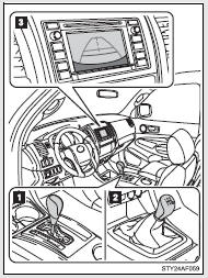
The rear view image is displayed when the shift position is in R and the engine switch is in the “ON” position.
The rear view monitor system will be deactivated when the shift lever is in any position other than R.
 Automatic transmission
 Manual transmission
 Screen
Using the rear view monitor system
■ Screen description
 Vehicle width guide lines
The line indicates a guide path when the vehicle is being backed straight up.
The displayed width is wider than the actual vehicle width.
 Vehicle center guide lines
These lines indicate the estimated vehicle center on the ground.
 Distance guide line
The line shows points approximately 1.5 ft. (0.5 m) (red) from the center of the edge of the bumper.
 Distance guide line
The line shows distance behind the vehicle, a point approximately 3 ft.
(1 m) (blue) from the edge of the bumper.
Rear view monitor system precautions
■ Area displayed on screen
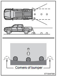
The rear view monitor system displays an image of the view from the bumper of the rear area of the vehicle.
To adjust the image on the rear view monitor system screen.
• The area displayed on the screen may vary according to vehicle orientation conditions.
• Objects which are close to either corner of the bumper or under the bumper cannot be seen on the screen.
• The camera uses a special lens.
The distance of the image that appears on the screen differs from the actual distance.
• Items which are located higher than the camera may not be displayed by the monitor.
■ Rear view monitor system camera
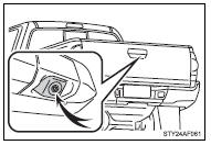
The camera for the rear view monitor system is located as shown in the illustration.
● Using the camera
If the camera lens becomes dirty, it cannot transmit a clear image.
If water droplets, snow or mud adhere to the lens, rinse it with water and wipe with a soft cloth. If the lens is extremely dirty, wash it with a mild cleanser and rinse.
■ Differences between the screen and the actual road
The distance guide lines and the vehicle width guide lines may not actually be parallel with the dividing lines of the parking space, even when they appear to be so. Be sure to check visually.
The distances between the vehicle width guide lines and the left and right dividing lines of the parking space may not be equal, even when they appear to be so. Be sure to check visually.
The distance guide lines give a distance guide for flat road surfaces.
In any of the following situations, there is a margin of error between the fixed guide lines on the screen and the actual distance/ course on the road.
● When the ground behind the vehicle slopes up sharply
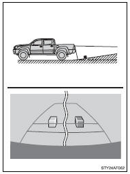
The distance guide lines will appear to be closer to the vehicle than the actual distance.
Because of this, objects will appear to be farther away than they actually are. In the same way, there will be a margin of error between the guidelines and the actual distance/course on the road.
● When the ground behind the vehicle slopes down sharply
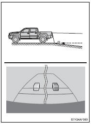
The distance guide lines will appear to be further from the vehicle than the actual distance.
Because of this, objects will appear to be closer than they actually are. In the same way, there will be a margin of error between the guidelines and the actual distance/course on the road.
● When any part of the vehicle sags
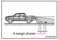
When any part of the vehicle sags due to the number of passengers or the distribution of the load, there is a margin of error between the fixed guide lines on the screen and the actual distance/ course on the road.
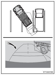
■ When approaching three-dimensional objects
The distance guide lines are displayed according to flat surfaced objects (such as the road). It is not possible to determine the position of three-dimensional objects (such as vehicles) using the distance guide lines. When approaching a three-dimensional object that extends outward (such as the flatbed of a truck), be careful of the following.
● Distance guidelines
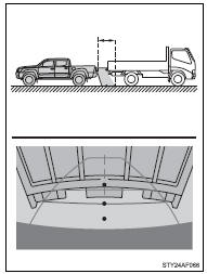
Visually check the surroundings and the area behind the vehicle.
On the screen, it appears that a truck is parked at point
 . However, in reality if you back
up to point
. However, in reality if you back
up to point  , you will hit the truck.
On the screen, it appears that
, you will hit the truck.
On the screen, it appears that  is
closest and
is
closest and  is furthest away.
However, in reality, the distance to
 and
and
 is the same, and
 is farther than
 and
and
 .
.
■ Vehicle width guide lines
Visually check the surroundings and the area behind the vehicle.
In the case shown below, the truck appears to be outside of the vehicle width guide lines and the vehicle does not look as if it hits the truck. However, the rear body of the truck may actually cross over the vehicle width guide lines. In reality if you back up as guided by the vehicle width guide lines, the vehicle may hit the truck.
Things you should know
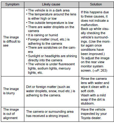
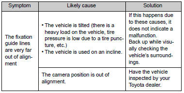
■ If you notice any symptoms
If you notice any of the following symptoms, refer to the likely cause and the solution, and re-check.
If the symptom is not resolved by the solution, have the vehicle inspected by your Toyota dealer.
CAUTION
■When using the rear view monitor system
The rear view monitor system is a supplemental device intended to assist the driver when backing up. When backing up, be sure to check visually behind and all around the vehicle before proceeding.
Observe the following precautions to avoid an accident that could result in death or serious injuries.
●Never depend on the rear view monitor system entirely when backing up.
The image and the position of the guide lines displayed on the screen may differ from the actual state.
Use caution, just as you would when backing up any vehicle.
●Be sure to back up slowly, depressing the brake pedal to control vehicle speed.
●The instructions given are only guidelines.
When and how much to turn the steering wheel will vary according to traffic conditions, road surface conditions, vehicle condition, etc., when parking.
It is necessary to be fully aware of this before using the rear view monitor system.
●When parking, be sure to check that the parking space will accommodate your vehicle before maneuvering into it.
●Do not use the rear view monitor system in the following cases:
• On icy or slick road surfaces, or in snow
• When using tire chains or the compact spare tire
• When the tailgate is not closed completely
• On roads that are not flat or straight, such as curves or slopes.
●In low temperatures, the screen may darken or the image may become faint. The image could distort when the vehicle is moving, or you may become unable to see the image on the screen. Be sure to directly check visually and with the mirrors all around the vehicle before proceeding.
●If the tire sizes are changed, the position of the fixed guide lines displayed on the screen may change.
●The camera uses a special lens. The distances between objects and pedestrians that appear in the image displayed on the screen will differ from the actual distances.
NOTICE
■How to use the camera
●The rear view monitor system may not operate properly in the following cases.
• If the back of the vehicle is hit, the position and mounting angle of the camera may change.
• As the camera has a water proof construction, do not detach, disassemble or modify it. This may cause incorrect operation.
• Do not strongly rub the camera lens. If the camera lens is scratched, it cannot transmit a clear image.
• Do not allow organic solvent, car wax, window cleaner or glass coat to adhere to the camera. If this happens, wipe it off as soon as possible.
• If the temperature changes rapidly, such as when hot water is poured on the vehicle in cold weather, the system may not operate normally.
• When washing the vehicle, do not apply intensive bursts of water to the camera or camera area. Doing so may result in the camera malfunctioning.
• When the camera is used under fluorescent lights, sodium light or mercury light, etc., the lights and the illuminated areas may appear to flicker.
●Do not expose the camera to strong impact as this could cause a malfunction.
If this happens, have the vehicle inspected by your Toyota dealer as soon as possible.
 Cruise control
Use the cruise control to maintain a set speed without depressing the accelerator
pedal.
Indicator
Cruise control switch
■ Setting the vehicle speed
Press the ON-OFF button to activa ...
 Four-wheel drive system
Use the front-wheel drive control switch to select the following transfer modes.
H2 (high speed position, two-wheel
drive)
Use this for normal driving on dry hard-surfaced roads.
This position ...
Other materials:
Removal
REMOVAL
PROCEDURE
1. REMOVE PROPELLER SHAFT WITH CENTER BEARING ASSEMBLY
(a) Place matchmarks on the propeller shaft flange and differential flange.
Text in Illustration
*a
Matchmark
...
Installation
INSTALLATION
PROCEDURE
1. INSTALL FRONT DIFFERENTIAL CARRIER ASSEMBLY
(a) Connect the actuator hose and connector.
(b) Install the No. 1 mounting support with the 3 bolts.
Torque:
186 N·m {1899 kgf·cm, 138 ft·lbf}
(c) Install the No. 2 mounting support with the 2 bolts.
Torque:
160 N ...
Runnable Signal Malfunction (B2286,P0335)
DESCRIPTION
These DTCs are stored when the engine speed signal sent by the ECM via direct
line and the engine speed signal sent via CAN communication do not match.
HINT:
When the cable is disconnected and reconnected to the negative (-) battery terminal,
the power source mode returns to the s ...
