Toyota Tacoma (2015-2018) Service Manual: Rear Airbag Sensor LH Circuit Malfunction (B1635/24)
DESCRIPTION
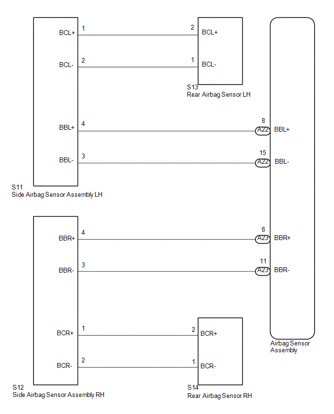
The airbag sensor LH consists of parts such as the safing sensor, the diagnostic circuit and the lateral deceleration sensor.
When the airbag sensor assembly receives signals from the lateral deceleration sensor, it determines whether or not the SRS should be activated.
DTC B1635/24 is set when a malfunction is detected in the side airbag sensor assembly LH and rear airbag sensor LH circuit.
|
DTC No. |
DTC Detections Conditions |
Trouble Areas |
|---|---|---|
|
B1635/24 |
|
|
WIRING DIAGRAM
CAUTION / NOTICE / HINT
NOTICE:
After turning the ignition switch off, waiting time may be required before disconnecting
the cable from the negative (-) battery terminal. Therefore, make sure to read the
disconnecting the cable from the negative (-) battery terminal notices before proceeding
with work (See page .gif) ).
).
PROCEDURE
|
1. |
CHECK CONNECTOR OF CONNECTORS |
(a) Turn the ignition switch off.
(b) Disconnect the negative (-) terminal cable from the battery, and wait for at least 90 seconds.
(c) Check that the connectors are properly connected to the side airbag sensor assembly LH and the rear airbag sensor LH.
OK:
The connectors are properly connected.
| NG | .gif) |
CONNECT CONNECTORS |
|
.gif)
|
2. |
CHECK CONNECTORS |
(a) Check that the connectors (on the side airbag sensor assembly LH side and
rear airbag sensor LH side) are not damaged (See page
).
OK:
The connectors are not deformed or damaged.
| NG | |
REPLACE WIRE HARNESS |
|
|
3. |
CHECK NO. 2 FLOOR WIRE (FOR OPEN) |
|
(a) Disconnect the connectors from the side airbag sensor assembly LH and the rear airbag sensor LH. |
|
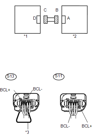
(b) Using service wire, connect S13-2 (BCL+) and S13-1 (BCL-) of connector C.
(c) Measure the resistance according to the value(s) in the table below.
Standard Resistance:
|
Tester Connection |
Condition |
Specified Condition |
|---|---|---|
|
S11-1 (BCL+) - S11-2 (BCL-) |
Always |
Below 1 Ω |
|
*1 |
Rear Airbag Sensor LH |
|
*2 |
Side Airbag Sensor Assembly LH |
|
*3 |
Service Wire |
| NG | |
REPLACE NO. 2 FLOOR WIRE |
|
|
4. |
CHECK NO. 2 FLOOR WIRE (FOR SHORT) |
|
(a) Disconnect the service wire from connector C. |
|
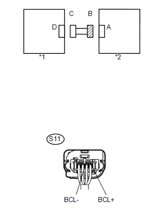
(b) Disconnect the connectors from the side airbag sensor assembly LH and rear airbag sensor LH.
(c) Measure the resistance according to the value(s) in the table below.
Standard Resistance:
|
Tester Connection |
Condition |
Specified Condition |
|---|---|---|
|
S11-1 (BCL+) - S11-2 (BCL-) |
Always |
1 MΩ or Higher |
|
*1 |
Rear Airbag Sensor LH |
|
*2 |
Side Airbag Sensor Assembly LH |
| NG | |
REPLACE NO. 2 FLOOR WIRE |
|
|
5. |
CHECK NO. 2 FLOOR WIRE (TO B+) |
|
(a) Connect the negative (-) terminal cable to the battery, and wait for at least 2 seconds. |
|
(b) Turn the ignition switch to ON.
(c) Measure the voltage according to the value(s) in the table below.
Standard Voltage:
|
Tester Connection |
Switch Condition |
Specified Condition |
|---|---|---|
|
S11-1 (BCL+) - Body ground |
Ignition switch ON |
Below 1 V |
|
S11-2 (BCL-) - Body ground |
Ignition switch ON |
Below 1 V |
|
*1 |
Rear Airbag Sensor LH |
|
*2 |
Side Airbag Sensor Assembly LH |
| NG | |
REPLACE NO. 2 FLOOR WIRE |
|
|
6. |
CHECK NO. 2 FLOOR WIRE (TO GROUND) |
|
(a) Turn the ignition switch off. |
|
(b) Disconnect the negative (-) terminal cable from the battery, and wait for at least 90 seconds.
(c) Measure the resistance according to the value(s) in the table below.
Standard Resistance:
|
Tester Connection |
Condition |
Specified Condition |
|---|---|---|
|
S11-1 (BCL+) - Body ground |
Always |
1 MΩ or Higher |
|
S11-2 (BCL-) - Body ground |
Always |
1 MΩ or Higher |
|
*1 |
Rear Airbag Sensor LH |
|
*2 |
Side Airbag Sensor Assembly LH |
| NG | |
REPLACE NO. 2 FLOOR WIRE |
|
|
7. |
CHECK REAR AIRBAG SENSOR LH |
(a) Connect the connector to the side airbag sensor assembly LH.
(b) Interchange the rear airbag sensor LH with the rear airbag sensor RH and connect the connectors to them.
(c) Connect the negative (-) terminal cable to the battery, and wait for at least 2 seconds.
(d) Turn the ignition switch to ON, and wait for at least 60 seconds.
(e) Clear any DTCs stored in the memory (See page
).
(f) Turn the ignition switch off.
(g) Turn the ignition switch to ON, and wait for at least 60 seconds.
(h) Check for DTCs (See page ).
|
Result |
Proceed to |
|---|---|
|
DTC B1635/24 is output. |
A |
|
DTC B1630/23 is output. |
B |
|
Neither DTC B1630/23 nor B1635/24 is output. |
C |
| B | |
REPLACE REAR AIRBAG SENSOR LH |
| C | |
USE SIMULATION METHOD TO CHECK |
|
|
8. |
CHECK SIDE AIRBAG SENSOR ASSEMBLY LH |
(a) Turn the ignition switch off.
(b) Disconnect the negative (-) terminal cable from the battery, and wait for at least 90 seconds.
(c) Return the rear airbag sensor LH and RH to their original positions and connect the connectors to them.
(d) Interchange the side airbag sensor assembly LH with the side airbag sensor assembly RH and connect the connectors to them.
(e) Connect the negative (-) terminal cable to the battery, and wait for at least 2 seconds.
(f) Turn the ignition switch to ON, and wait for at least 60 seconds.
(g) Clear any DTCs stored in the memory (See page
).
(h) Turn the ignition switch off.
(i) Turn the ignition switch to ON, and wait for at least 60 seconds.
(j) Check for DTCs (See page ).
|
Result |
Proceed to |
|---|---|
|
DTC B1635/24 is output. |
A |
|
DTC B1630/23 is output. |
B |
|
Neither DTC B1630/23 nor B1635/24 is output. |
C |
HINT:
DTCs other than B1630/23 and B1635/24 may be output at this time, but they are not related to this check.
| B | |
REPLACE REAR AIRBAG SENSOR LH |
| C | |
USE SIMULATION METHOD TO CHECK |
|
|
9. |
REPLACE AIRBAG SENSOR ASSEMBLY |
(a) Turn the ignition switch off.
(b) Disconnect the negative (-) terminal cable from the battery, and wait for at least 90 seconds.
(c) Replace the airbag sensor assembly (See page
).
HINT:
Perform the inspection using parts from a normal vehicle when possible.
(d) Connect the connectors to the airbag sensor assembly.
(e) Connect the negative (-) terminal cable to the battery, and wait for at least 2 seconds.
(f) Turn the ignition switch to ON, and wait for at least 60 seconds.
(g) Clear any DTCs stored in the memory (See page
).
(h) Turn the ignition switch off.
(i) Turn the ignition switch to ON, and wait for at least 60 seconds.
(j) Check for DTCs (See page ).
OK:
DTC B1635/24 is not output.
HINT:
DTCs other than B1635/24 may be output at this time, but they are not related to this check.
Result|
Result |
Proceed to |
|---|---|
|
NG |
A |
|
OK |
B |
| B | |
END |
|
|
10. |
CHECK REAR AIRBAG SENSOR LH |
(a) Turn the ignition switch off.
(b) Disconnect the negative (-) terminal cable from the battery, and wait for at least 90 seconds.
(c) Replace the rear airbag sensor LH for Double Cab (See page
) or for Access
Cab (See page
).
(d) Connect the connectors to the airbag sensor assembly.
(e) Connect the negative (-) terminal cable to the battery, and wait for at least 2 seconds.
(f) Turn the ignition switch to ON, and wait for at least 60 seconds.
(g) Clear any DTCs stored in the memory (See page
).
(h) Turn the ignition switch off.
(i) Turn the ignition switch to ON, and wait for at least 60 seconds.
(j) Check for DTCs (See page ).
OK:
DTC B1635/24 is not output.
HINT:
DTCs other than B1635/24 may be output at this time, but they are not related to this check.
| OK | |
END |
| NG | |
REPLACE SIDE AIRBAG SENSOR ASSEMBLY LH |
 Rear Airbag Sensor RH Circuit Malfunction (B1630/23)
DESCRIPTION
The airbag sensor RH consists of parts such as the safing sensor, the diagnostic
circuit and the lateral deceleration sensor.
When the airbag sensor assembly receives signals from the ...
 Center Airbag Sensor Assembly Malfunction (B1000/31)
DESCRIPTION
The airbag sensor assembly consists of a deceleration sensor, safing sensor,
drive circuit, diagnosis circuit, ignition control, etc.
If the airbag sensor assembly receives signals fro ...
Other materials:
Disassembly
DISASSEMBLY
CAUTION / NOTICE / HINT
NOTICE:
Do not try to remove the black nylon tube as it is welded to the fuel suction
tube assembly (See page
).
PROCEDURE
1. REMOVE FUEL SENDER GAUGE ASSEMBLY
2. REMOVE NO. 1 FUEL SUB-TANK
(a) Disconnect the 2 fuel pump connectors.
...
Front Upper Suspension Arm
Components
COMPONENTS
ILLUSTRATION
Disassembly
DISASSEMBLY
PROCEDURE
1. REMOVE FRONT SUSPENSION UPPER ARM BUSH
(a) Using a hammer and chisel, raise the flange of the bushing diagonally as
shown in the illustration.
(b) Using SST and a press, remove the front suspension u ...
Engine Immobiliser System Malfunction (B2799,B279986)
DESCRIPTION
This DTC is stored when one of the following occurs: 1) the ECM detects errors
in its own communication with the transponder key ECU assembly; 2) the ECM detects
errors in the communication lines; or 3) the ECU communication ID between the transponder
key ECU assembly and ECM is d ...
