Toyota Tacoma (2015-2018) Service Manual: Purge Valve
Components
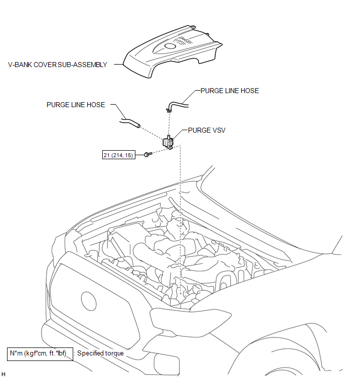
COMPONENTS
ILLUSTRATION
Inspection
INSPECTION
PROCEDURE
1. INSPECT PURGE VSV
|
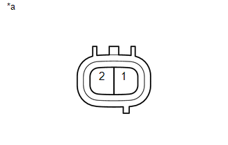
(a) Measure the resistance according to the value(s) in the table below. Text in Illustration
Standard Resistance:
If the result is not as specified, replace the purge VSV. |
|
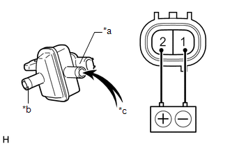
(b) Check the operation of the purge VSV.
|
(1) Apply battery voltage between the terminals of the purge VSV and check that the following occurs when blowing air into the port (E). Text in Illustration
OK:
If the result is not as specified, replace the purge VSV. |
|
Removal
REMOVAL
PROCEDURE
1. REMOVE V-BANK COVER SUB-ASSEMBLY
.gif)
2. REMOVE PURGE VSV
|
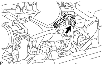
(a) Slide the hose clip and disconnect the purge line hose from the purge VSV. |
|
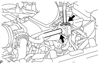
(b) Disconnect the purge line hose from the purge VSV.
|
(c) Disconnect the connector from the purge VSV. |
|
|
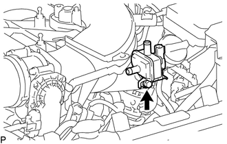
(d) Remove the bolt and purge VSV from the intake air surge tank. |
|
Installation
INSTALLATION
PROCEDURE
1. INSTALL PURGE VSV
(a) Install the purge VSV to the intake air surge tank with the bolt.
Torque:
21 N·m {214 kgf·cm, 15 ft·lbf}
(b) Connect the purge line hose to the purge VSV, and slide the hose clip to secure it.
(c) Connect the purge line hose to the purge VSV.
(d) Connect the connector to the purge VSV.
2. INSTALL V-BANK COVER SUB-ASSEMBLY
.gif)
 Pcv Valve
Components
COMPONENTS
ILLUSTRATION
Inspection
INSPECTION
PROCEDURE
1. INSPECT PCV VALVE SUB-ASSEMBLY
(a) Install a clean hose to the PCV valve sub-assembly.
(b) Check the PCV valve sub-a ...

Other materials:
Some Alarm Functions do not Operate
DESCRIPTION
When the alarm sounds, the following alarm functions operate: the roof console
box assembly and No. 1 room light assembly illuminates, and the headlights, taillights
and hazard lights flash, and the security horn and vehicle horn sound intermittently.
WIRING DIAGRAM
CAUTION / ...
Installation
INSTALLATION
PROCEDURE
1. INSTALL AIR CONDITIONING UNIT ASSEMBLY
(a) Temporary install the air conditioning unit assembly.
(b) Insert the bracket hook into the holes of the reinforcement bracket, and
temporary install the instrument panel reinforcement assembly.
(c) Install the instrument p ...
Acceleration Sensor Stuck Malfunction (C1232,C1243,C1245)
DESCRIPTION
The skid control ECU (brake actuator assembly) receives signals from the yaw
rate and acceleration sensor (airbag sensor assembly) via the CAN communication
system.
The airbag sensor assembly has a built-in acceleration sensor and detects the
vehicle condition.
If there is troub ...
