Toyota Tacoma (2015-2018) Service Manual: Pattern Select Switch Power Mode Circuit
DESCRIPTION
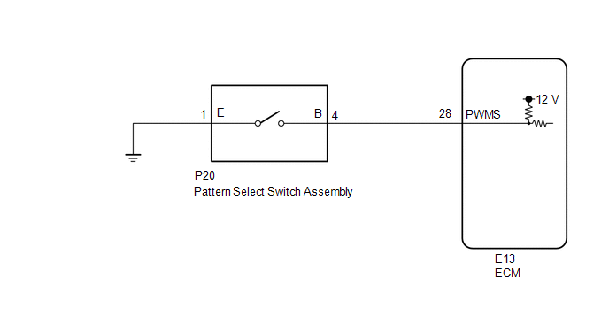
The ECM memory contains the programs for the normal and PWR shift patterns.
By following the programs corresponding to the signals from the pattern select switch assembly, park/neutral position switch and other various sensors, the ECM switches the shift solenoid valves on and off, and controls the transmission gear ratio.
WIRING DIAGRAM
PROCEDURE
|
1. |
INSPECT PATTERN SELECT SWITCH ASSEMBLY |
|
(a) Remove the pattern select switch assembly (See page
|
|
.gif) ).
).
(b) Measure the resistance according to the value(s) in the table below.
Standard Resistance:
|
Tester Connection |
Switch Condition |
Specified Condition |
|---|---|---|
|
1 (E) - 4 (B) |
Pattern select switch assembly pushed |
Below 1 Ω |
|
1 (E) - 4 (B) |
Pattern select switch assembly not pushed |
10 kΩ or higher |
|
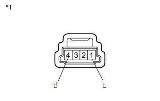
*1 |
Pattern Select Switch Assembly |
| NG | .gif) |
REPLACE PATTERN SELECT SWITCH ASSEMBLY |
|
.gif)
|
2. |
CHECK HARNESS AND CONNECTOR (PATTERN SELECT SWITCH ASSEMBLY - BODY GROUND) |
|
(a) Disconnect the pattern select switch assembly connector. |
|
(b) Measure the resistance according to the value(s) in the table below.
Standard Resistance:
|
Tester Connection |
Condition |
Specified Condition |
|---|---|---|
|
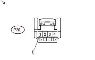
P20-1 (E) - Body ground |
Always |
Below 1 Ω |
|
*a |
Front view of wire harness connector (to Pattern Select Switch Assembly) |
| NG | |
REPAIR OR REPLACE HARNESS OR CONNECTOR |
|
|
3. |
CHECK HARNESS AND CONNECTOR (PATTERN SELECT SWITCH ASSEMBLY - ECM) |
|
(a) Disconnect the ECM connector. |
|
(b) Measure the resistance according to the value(s) in the table below.
Standard Resistance:
|
Tester Connection |
Switch Condition |
Specified Condition |
|---|---|---|
|
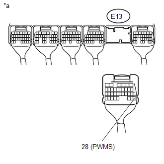
E13-28 (PWMS) - Body ground |
Pattern select switch assembly pushed |
Below 1 Ω |
|
E13-28 (PWMS) - Body ground |
Pattern select switch assembly not pushed |
10 kΩ or higher |
|
*a |
Rear view of wire harness connector (to ECM) |
| OK | |
PROCEED TO NEXT SUSPECTED AREA SHOWN IN PROBLEM SYMPTOMS TABLE |
| NG | |
REPAIR OR REPLACE HARNESS OR CONNECTOR |
 Torque Converter Clutch Pressure Control Solenoid Control Circuit Open (P275613)
DESCRIPTION
Refer to the system description for DTC P27567F (See page
).
DTC No.
DTC Detection Condition
Trouble Area
SAE
P275613
...

Other materials:
If the vehicle battery is discharged
The following procedures may be used to start the engine if the vehicle’s
battery is discharged.
You can call your Toyota dealer or qualified repair shop.
If you have a set of jumper (or booster) cables and a second vehicle with a 12-volt
battery, you can jump start your Toyota following the ...
Freeze Frame Data
FREEZE FRAME DATA
1. FREEZE FRAME DATA
(a) Using the Techstream, check the vehicle condition (ECU, sensor) when the
brake system operates or a DTC is output.
2. CHECK FREEZE FRAME DATA WHEN BRAKE SYSTEM OPERATES
(a) Freeze frame data is stored when the brake system operates. The freeze frame
...
Customize Parameters
CUSTOMIZE PARAMETERS
1. CUSTOMIZE POWER DOOR LOCK CONTROL SYSTEM
HINT:
The following items can be customized.
NOTICE:
When the customer requests a change in a function, first make sure that
the function can be customized.
Be sure to make a note of the current settings before cus ...
