Toyota Tacoma (2015-2018) Service Manual: Parts Location
PARTS LOCATION
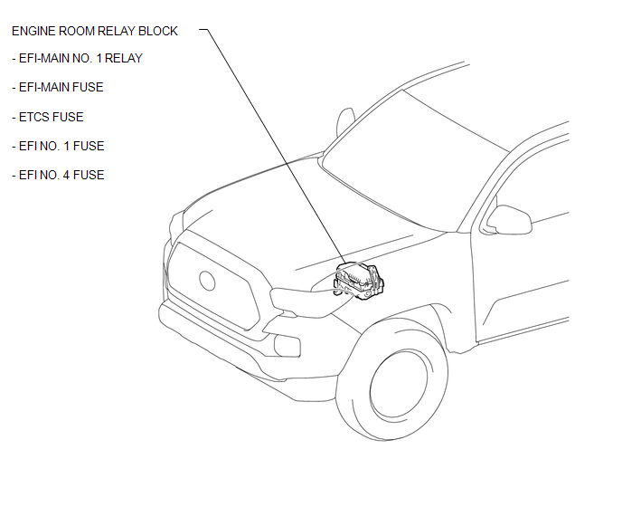
ILLUSTRATION
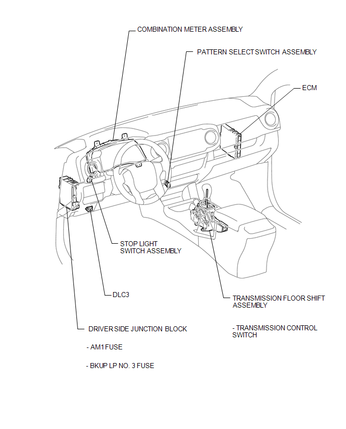
ILLUSTRATION
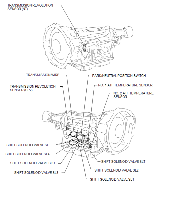
ILLUSTRATION
 Definition Of Terms
DEFINITION OF TERMS
Term
Definition
Monitor description
Description of what the ECM monitors and how it detects malfunctions
(monitoring purpose ...
 Precaution
PRECAUTION
1. IGNITION SWITCH EXPRESSION
HINT:
The type of ignition switch used on this model differs depending on the specifications
of the vehicle. The expressions listed in the table below are ...
Other materials:
Air Inlet Control Servo Motor
Inspection
INSPECTION
PROCEDURE
1. INSPECT AIR INLET CONTROL SERVO MOTOR
(a) Inspect the servo motor operation.
(1) Connect the positive (+) lead from the battery to terminal 1 (FRS)
and negative (-) lead to terminals 2 (REC), then check that the shaft rotates
clockwise s ...
Dtc Check / Clear
DTC CHECK / CLEAR
1. CHECK DTC
(a) Connect the Techstream to the DLC3.
(b) Turn the ignition switch to ON.
(c) Turn the back sonar or clearance sonar switch assembly on.
(d) Turn the Techstream on.
(e) Enter the following menus: Body Electrical / Intuitive P/A / Trouble Codes.
(f) Check for D ...
Data List / Active Test
DATA LIST / ACTIVE TEST
HINT:
By accessing the Data List displayed on the Techstream, you can perform such
functions as reading the values of switches and sensors without removing any parts.
Reading the Data List is the first step of troubleshooting and is one method to
shorten labor time.
...
