Toyota Tacoma (2015-2018) Service Manual: Parts Location
PARTS LOCATION
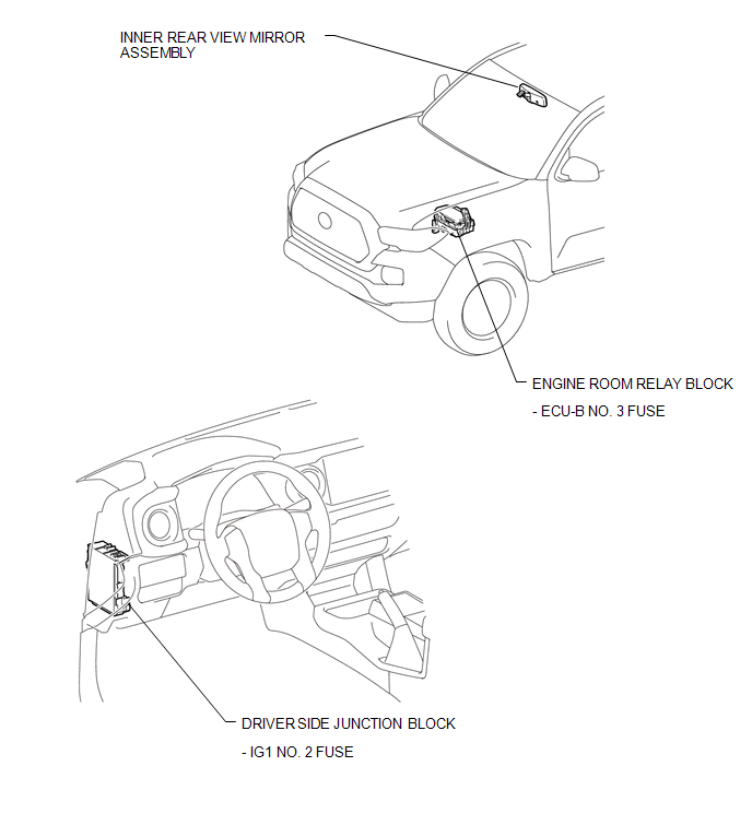
ILLUSTRATION

 System Diagram
SYSTEM DIAGRAM
...
Other materials:
Reassembly
REASSEMBLY
CAUTION / NOTICE / HINT
HINT:
Perform "Inspection After Repairs" after replacing the cylinder head sub-assembly
or cylinder head LH (See page ).
PROCEDURE
1. INSTALL SPARK PLUG TUBE
NOTICE:
When using a new cylinder head, the spark plug tubes must be replaced.
...
Dtc Check / Clear
DTC CHECK / CLEAR
NOTICE:
When the diagnosis system is changed from normal mode to check mode or vice versa,
all DTCs and freeze frame data recorded in normal mode are cleared. Before changing
modes, always check and make a note of DTCs and freeze frame data.
HINT:
DTCs which are sto ...
Diagnostic Trouble Code Chart
DIAGNOSTIC TROUBLE CODE CHART
Blind Spot Monitor System
DTC Code
Detection Item
See page
C1A45
Vehicle Speed Sensor
C1A47
Steering Angle Sensor
C1AB0
Short ...
