Toyota Tacoma (2015-2018) Service Manual: Parts Location
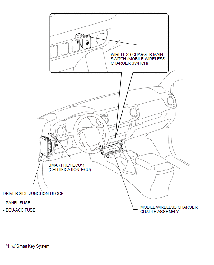
PARTS LOCATION
ILLUSTRATION
 Precaution
PRECAUTION
1. IGNITION SWITCH EXPRESSIONS
(a) The type of ignition switch used on this model differs according to the specifications
of the vehicle. The expressions listed in the table below are u ...
 System Description
SYSTEM DESCRIPTION
1. WIRELESS CHARGER FUNCTION OUTLINE
(a) The wireless charging system enables Qi-compliant* rechargeable devices,
such as a cellular phone, to be recharged by merely placing it ...
Other materials:
Lost Communication with Alternator Missing Message (P161A87)
DESCRIPTION
The ECM communicates with the generator assembly via LIN communication. If a
LIN communication error is detected, the ECM stores this DTC.
DTC No.
DTC Detection Condition
Trouble Area
P161A87
Generator assembly or ECM commu ...
Check Bus 3 Lines for Short Circuit
DESCRIPTION
There may be a short circuit between the CAN main bus lines and/or CAN branch
lines when the resistance between terminals 6 (CA3H) and 21 (CA3L) of the central
gateway ECU (network gateway ECU) is below 54 Ω.
Detection Item
Trouble Area
Resis ...
Off-road precautions (4WD models and PreRunner)
This vehicle has higher ground clearance and narrower tread in relation to
the height of its center of gravity to make it capable of performing in a wide variety
of off-road applications.
Off-road vehicle feature
● Specific design characteristics give it a higher center of gravity than o ...
