Toyota Tacoma (2015-2018) Service Manual: Parts Location
PARTS LOCATION
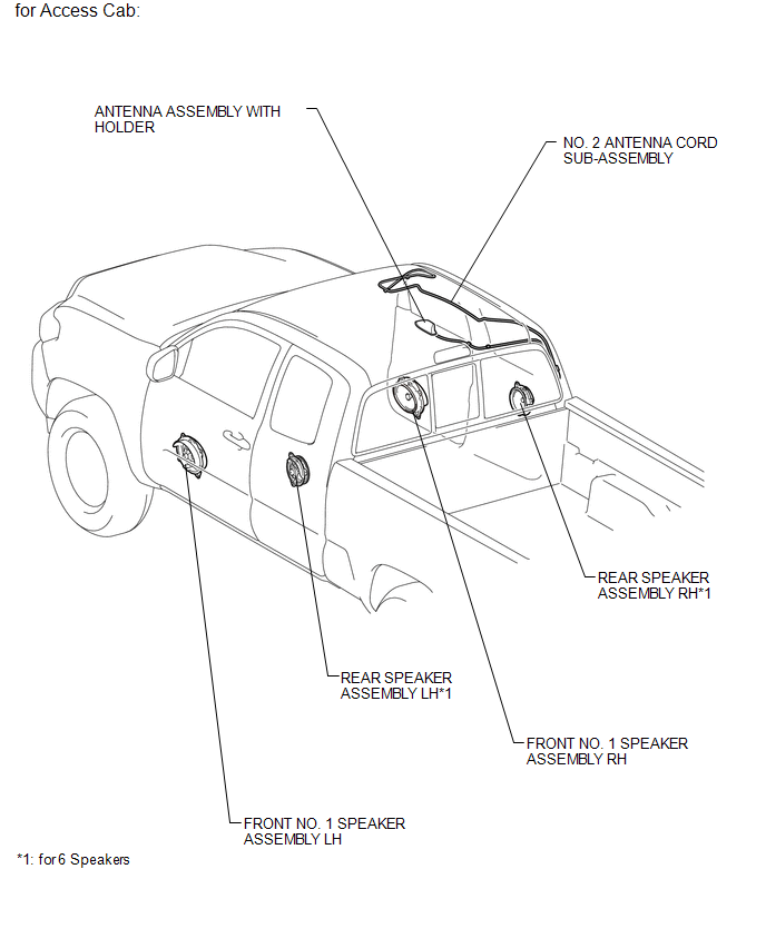
ILLUSTRATION

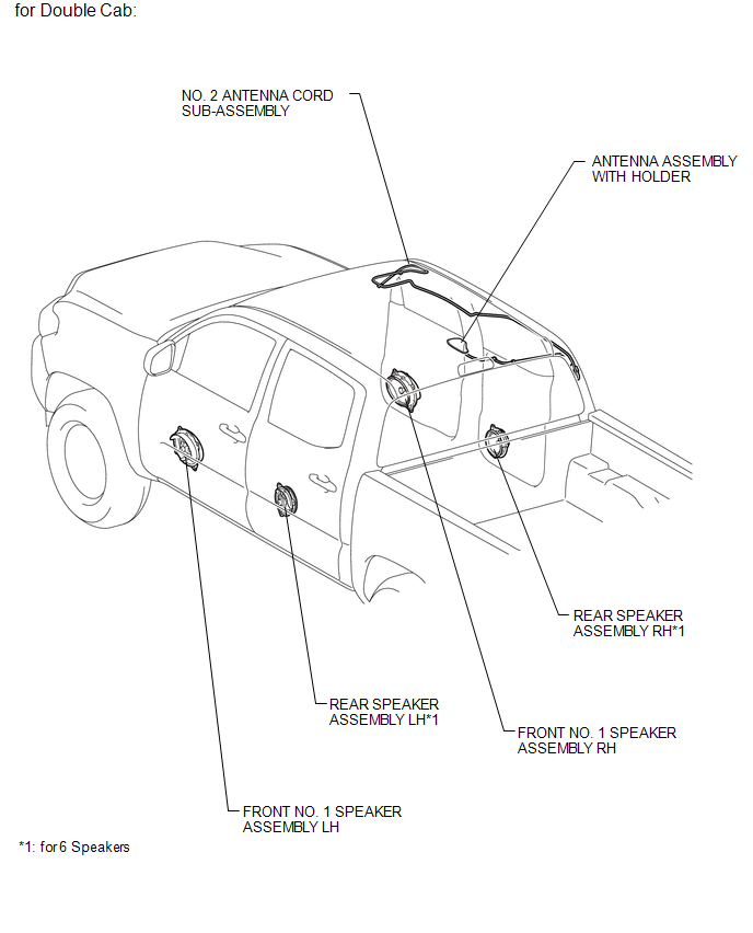
ILLUSTRATION
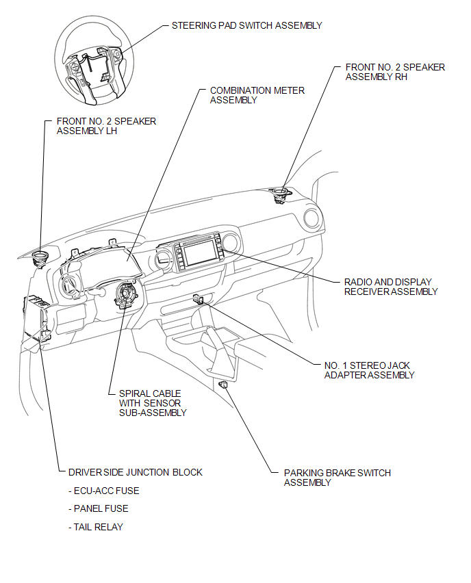
ILLUSTRATION
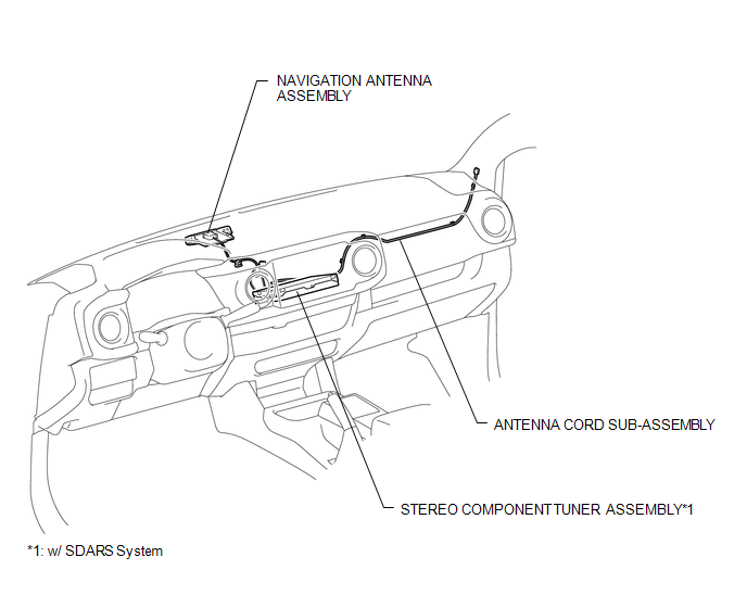
ILLUSTRATION
ILLUSTRATION
 Precaution
PRECAUTION
1. IGNITION SWITCH EXPRESSIONS
(a) The type of ignition switch used on this model differs according to the specifications
of the vehicle. The expressions listed in the table below are u ...
 System Diagram
SYSTEM DIAGRAM
...
Other materials:
Air Outlet Control Servo Motor
Inspection
INSPECTION
PROCEDURE
1. INSPECT MODE CONTROL SERVO MOTOR
(a) Inspect the servo motor operation.
(1) When 12V is applied between terminals 4 (IGN) and 1 (GND), and 0V
is applied between terminals 2 (SIG) and 1 (GND), check that the line connecting
the 2 notches ...
Clearance Sonar Main Switch
Components
COMPONENTS
ILLUSTRATION
Removal
REMOVAL
PROCEDURE
1. REMOVE INSTRUMENT PANEL LOWER CENTER FINISH PANEL
(See page )
2. REMOVE BACK SONAR OR CLEARANCE SONAR SWITCH ASSEMBLY
(a) Disengage the 2 claws to remove the back sonar or clearance sonar
switch assembly.
...
Engine Switch
Components
COMPONENTS
ILLUSTRATION
Inspection
INSPECTION
PROCEDURE
1. INSPECT ENGINE SWITCH
(a) Measure the resistance according to the value(s) in the table below.
Text in Illustration
*a
Component without harness connected
(Engine Switch)
-
...
