Toyota Tacoma (2015-2018) Service Manual: Parts Location
PARTS LOCATION
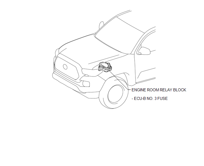
ILLUSTRATION
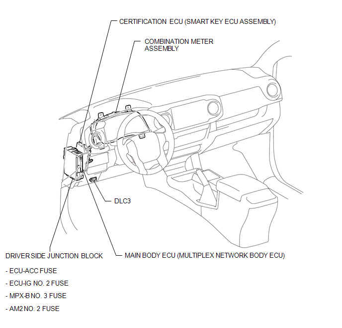
ILLUSTRATION
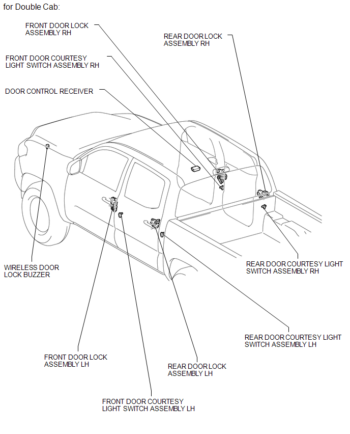
ILLUSTRATION
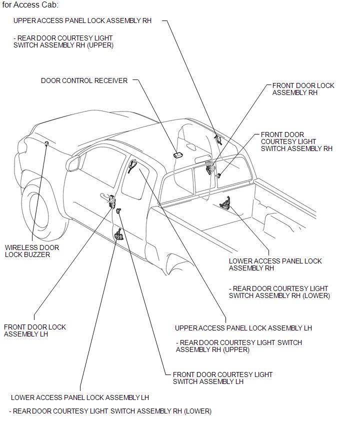
ILLUSTRATION

 Precaution
PRECAUTION
1. PRECAUTIONS WHEN USING TECHSTREAM
(a) When using the Techstream with the engine switch off to troubleshoot:
Connect the Techstream to the vehicle, and turn a courtesy light switch on ...
Other materials:
Diagnosis System
DIAGNOSIS SYSTEM
1. DESCRIPTION
The 4 wheel drive control ECU records DTCs when the ECU detects a malfunction
in the ECU itself or in system circuits.
The DTCs can be read through the DLC3 of the vehicle. When the system seems to
be malfunctioning, use the Techstream to check for malfunctions ...
Cursor or Map Rotates when Vehicle Stopped
PROCEDURE
1.
CHECK CONDITION
(a) Check with the customer if the vehicle has been turned by a turntable.
OK:
Vehicle has not been turned by a turntable.
HINT:
If the vehicle is turned on a turntable with the ignition switch ON,
the system ...
Data List / Active Test
DATA LIST / ACTIVE TEST
1. DATA LIST
HINT:
Using the Techstream to read the Data List allows the values or states of switches,
sensors, actuators and other items to be read without removing any parts. This non-intrusive
inspection can be very useful because intermittent conditions or signals ...
