Toyota Tacoma (2015-2018) Service Manual: Parts Location
PARTS LOCATION
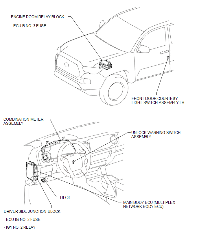
ILLUSTRATION

 System Diagram
SYSTEM DIAGRAM
...
Other materials:
Maintenance requirements
To ensure safe and economical driving, day-to-day care and regular maintenance
is essential. It is the owner’s responsibility to perform regular checks. Toyota
recommends the following maintenance.
■ General maintenance
Should be performed on a daily basis. This can be done by yourself ...
Transmitter ID1 Operation Stop (C2111/11-C2114/14)
DESCRIPTION
The tire pressure warning valve and transmitters that are installed in the tire
and wheel assemblies measure the tire pressure of each wheel. The measured values
are transmitted to the tire pressure warning ECU and receiver in the vehicle as
radio waves. The ECU compares the measu ...
How To Proceed With Troubleshooting
CAUTION / NOTICE / HINT
HINT:
Use the following procedure to troubleshoot the power mirror control
system.
*: Use the Techstream.
PROCEDURE
1.
VEHICLE BROUGHT TO WORKSHOP
NEXT
...
