Toyota Tacoma (2015-2018) Service Manual: Parts Location
PARTS LOCATION
ILLUSTRATION
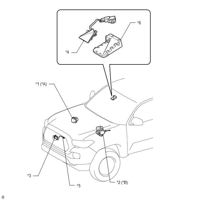
|
*A |
for Vacuum Brake Booster |
*B |
for Hydraulic Brake Booster |
|
*1 |
SKID CONTROL ECU (BRAKE ACTUATOR ASSEMBLY) |
*2 |
SKID CONTROL ECU (MASTER CYLINDER SOLENOID) |
|
*3 |
MILLIMETER WAVE RADAR SENSOR ASSEMBLY |
*4 |
CAMERA HEATER (FORWARD RECOGNITION HOOD) |
|
*5 |
MILLIMETER WAVE RADAR WIRE |
*6 |
FORWARD RECOGNITION CAMERA |
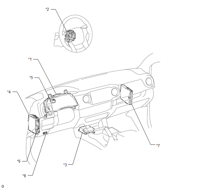
ILLUSTRATION
|
*1 |
COMBINATION METER ASSEMBLY |
*2 |
SPIRAL CABLE WITH SENSOR SUB-ASSEMBLY |
|
*3 |
YAW RATE AND ACCELERATION SENSOR (AIRBAG SENSOR ASSEMBLY) |
*4 |
DRIVER SIDE JUNCTION BLOCK - ECU-IG NO. 2 FUSE - IG1 NO. 2 FUSE |
|
*5 |
SKID CONTROL BUZZER |
*6 |
MAIN BODY ECU (MULTIPLEX NETWORK BODY ECU) |
|
*7 |
ECM |
*8 |
DLC3 |
 Precaution
PRECAUTION
PRECAUTION WHEN REPLACING COMBINATION METER ASSEMBLY
(a) When replacing the combination meter assembly, always replace it with a new
one. If a combination meter assembly which was insta ...
 System Description
SYSTEM DESCRIPTION
GENERAL DESCRIPTION
(a) The forward recognition camera processes the image captured by the monocular
camera to detect lane markers, vehicles, pedestrians, traffic signs, etc. Th ...
Other materials:
Diagnostic Trouble Code Chart
DIAGNOSTIC TROUBLE CODE CHART
Dynamic Radar Cruise Control System
DTC No.
Detection Item
MIL
Link
C1A02
Vehicle Information Not Obtained
Does not come on
C1A0A
Front Radar Se ...
ECM Communication Stop Mode
DESCRIPTION
Detection Item
Symptom
Trouble Area
ECM Communication Stop Mode
Either condition is met:
Communication stop for "ECM (Engine)" is indicated on the "Communication
Bus Check" screen of the ...
Skid Control Buzzer Circuit (C1A4A)
DESCRIPTION
Based on dynamic radar cruise control system operation, the forward recognition
camera provides warnings to the driver by sounding the skid control buzzer.
DTC C1A4A is stored when a malfunction is detected in the skid control buzzer
circuit.
DTC No.
Detectio ...
