Toyota Tacoma (2015-2018) Service Manual: Open in Rear Floor Electrical Key Oscillator Circuit (B27A6)
DESCRIPTION
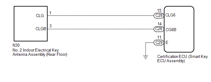
The certification ECU (smart key ECU assembly) generates a request signal and transmits the signal to the No. 2 indoor electrical key antenna assembly (rear floor). For the No. 2 indoor electrical key antenna assembly (rear floor) to detect when the electrical key transmitter sub-assembly is inside the vehicle, the signal from the certification ECU (smart key ECU assembly) requesting a response from the electrical key transmitter sub-assembly is transmitted inside the vehicle. DTC B27A6 is stored by the certification ECU (smart key ECU assembly) when an open circuit is detected between the certification ECU (smart key ECU assembly) and No. 2 indoor electrical key antenna assembly (rear floor) (between terminals CLG6 and CLG, or terminals CG6B and CLGB).
|
DTC Code |
DTC Detection Condition |
Trouble Area |
DTC Output Confirmation Operation |
|---|---|---|---|
|
B27A6 |
An open circuit is detected in the circuit between the certification ECU (smart key ECU assembly) and No. 2 indoor electrical key antenna assembly (rear floor) (CLG6 - CLG, CG6B - CLGB) (1 trip detection logic*). |
|
Any time |
- *: Only output while a malfunction is present.
|
Vehicle Condition when Malfunction Detected |
Fail-safe Operation when Malfunction Detected |
|---|---|
|
When electrical key transmitter sub-assembly is in rear seat area:
|
- |
|
DTC Code |
Data List and Active Test |
|---|---|
|
B27A6 |
Key diagnostic mode can be used to perform troubleshooting |
WIRING DIAGRAM
CAUTION / NOTICE / HINT
NOTICE:
- The smart key system (for Entry Function) uses the LIN communication
system and CAN communication system. Inspect the communication function
by following How to Proceed with Troubleshooting. Troubleshoot the smart
key system (for Entry Function) after confirming that the communication
systems are functioning properly (See page
.gif) ).
). - When using the Techstream with the engine switch off, connect the Techstream to the DLC3 and turn a courtesy light switch on and off at intervals of 1.5 seconds or less until communication between the Techstream and the vehicle begins. Then select the vehicle type under manual mode and enter the following menus: Body Electrical / Smart Key. While using the Techstream, periodically turn a courtesy light switch on and off at intervals of 1.5 seconds or less to maintain communication between the Techstream and the vehicle.
- Before replacing the certification ECU (smart key ECU assembly), refer
to smart key system (for Entry Function) Precaution (See page
).
- After repair, confirm that no DTCs are output by performing "DTC Output Confirmation Operation".
PROCEDURE
|
1. |
CHECK CONNECTOR CONNECTION |
(a) Turn the engine switch off.
(b) Check that the connectors are properly connected to the certification ECU (smart key ECU assembly) and No. 2 indoor electrical key antenna assembly (rear floor).
OK:
Connectors are properly connected.
| NG | .gif) |
CONNECT CONNECTORS PROPERLY |
|
.gif)
|
2. |
CHECK HARNESS AND CONNECTOR (CERTIFICATION ECU - NO. 2 INDOORELECTRICAL KEY ANTENNA ASSEMBLY) |
(a) Disconnect the C28 and C29 certification ECU (smart key ECU assembly) connectors.
(b) Disconnect the N30 No. 2 indoor electrical key antenna assembly (rear floor) connector.
(c) Measure the resistance according to the value(s) in the table below.
Standard Resistance:
|
Tester Connection |
Condition |
Specified Condition |
|---|---|---|
|
C28-15 (CLG6) - N30-1 (CLG) |
Always |
Below 1 Ω |
|
C28-14 (CG6B) - N30-3 (CLGB) |
Always |
Below 1 Ω |
|
C29-11 (E) - Body ground |
Always |
Below 1 Ω |
|
C28-15 (CLG6) or N30-1 (CLG) - Body ground |
Always |
10 kΩ or higher |
|
C28-14 (CG6B) or N30-3 (CLGB) - Body ground |
Always |
10 kΩ or higher |
| NG | |
REPAIR OR REPLACE HARNESS OR CONNECTOR |
|
|
3. |
CHECK CERTIFICATION ECU (SMART KEY ECU ASSEMBLY) (OUTPUT TO NO. 2 INDOORELECTRICAL KEY ANTENNA ASSEMBLY) |
(a) Connect the C28 and C29 certification ECU (smart key ECU assembly) connectors.
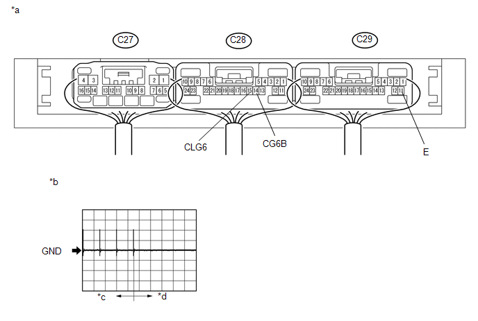 Text in Illustration
|
*a |
Component with harness connected (Certification ECU (smart key ECU assembly)) |
*b |
Waveform 1 |
|
*c |
For 30 seconds after closing any door using the door outside handle |
*d |
30 seconds or more have elapsed after closing any door using the door outside handle |
(b) Connect the N30 No. 2 indoor electrical key antenna assembly (rear floor) connector.
(c) Using an oscilloscope, check the waveform.
OK:
|
Tester Connection |
Switch Condition |
Tool Setting |
Tool Setting |
|---|---|---|---|
|
C28-15 (CLG6) - C29-11 (E) |
Procedure:
|
2 V/DIV., 500 ms./DIV. |
Pulse generation (See waveform 1) |
|
C28-14 (CG6B) - C29-11 (E) |
Procedure:
|
2 V/DIV., 500 ms./DIV. |
Pulse generation (See waveform 1) |
| NG | |
REPLACE CERTIFICATION ECU (SMART KEY ECU ASSEMBLY) |
|
|
4. |
REPLACE NO. 2 INDOOR ELECTRICAL KEY ANTENNA ASSEMBLY (REAR FLOOR) |
(a) Temporarily replace the No. 2 indoor electrical key antenna assembly (rear
floor) with a new or known good one (See page ).
|
|
5. |
CLEAR DTC |
(a) Clear the DTCs (See page ).
|
|
6. |
CHECK FOR DTC |
(a) Check for DTCs (See page ).
OK:
DTC B27A6 is not output.
| OK | |
END (NO. 2 INDOOR ELECTRICAL KEY ANTENNA ASSEMBLY (REAR FLOOR) WAS DEFECTIVE) |
| NG | |
REPLACE CERTIFICATION ECU (SMART KEY ECU ASSEMBLY) |
 Open in Driver Side Electrical Antenna Circuit (B27A1)
DESCRIPTION
The certification ECU (smart key ECU assembly) generates a request signal and
transmits the signal to the front door outside handle assembly LH [electrical key
antenna] at intervals o ...
 All Door Entry Lock/Unlock Functions do not Operate, but Wireless Functions
Operate
All Door Entry Lock/Unlock Functions do not Operate, but Wireless Functions
Operate
DESCRIPTION
When the wireless operation can be used to lock and unlock the doors, communication
between the electrical key and TPMS receiver assembly and certification ECU (smart
key ECU assembly ...
Other materials:
Pressure Control Solenoid "G" Actuator Stuck Off (P28077F)
SYSTEM DESCRIPTION
The ECM uses the vehicle speed signal and signals from the transmission revolution
sensors (NT, SP2) to detect the actual gear (1st, 2nd, 3rd, 4th, 5th or 6th gear).
The ECM compares the actual gear with the shift schedule in the ECM memory to
detect mechanical problems of t ...
Parts Location
PARTS LOCATION
ILLUSTRATION
*A
for Hydraulic Brake Booster
*B
for Vacuum Brake Booster
*1
FORWARD RECOGNITION CAMERA
*2
MILLIMETER WAVE RADAR SENSOR ASSEMBLY
*3
HYDRAULIC BRA ...
Problem Symptoms Table
PROBLEM SYMPTOMS TABLE
NOTICE:
After replacing the stereo component tuner assembly of vehicles subscribed to
pay-type satellite radio broadcasts, XM radio ID registration is necessary (w/ SDARS
System).
HINT:
Use the table below to help determine the cause of problem symptoms.
If ...
