Toyota Tacoma (2015-2018) Service Manual: Installation
INSTALLATION
PROCEDURE
1. INSTALL NO. 1 FUEL TANK PROTECTOR
(a) Install the No. 1 fuel tank protector to the fuel tank assembly with the 4 clips.
2. INSTALL FUEL SUCTION TUBE SET GASKET
Click here .gif)
3. INSTALL FUEL SUCTION TUBE WITH PUMP AND GAUGE ASSEMBLY
Click here
4. INSTALL FUEL PUMP GAUGE RETAINER
Click here
5. INSTALL FUEL TANK MAIN TUBE SUB-ASSEMBLY
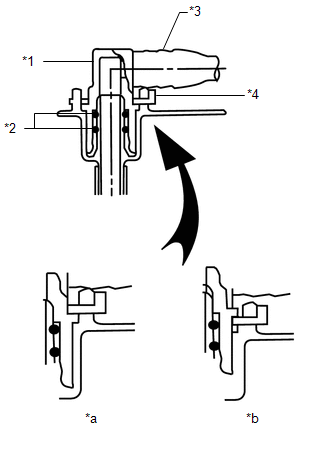
(a) Install the fuel tank main tube sub-assembly with the fuel tube joint clip.
NOTICE:
- Check that there are no scratches or foreign objects on the connecting parts.
- Check that the fuel tube joint are inserted securely.
- Check that the tube joint clip are on the collar of the fuel tube joint.
- After installing the tube joint clip, check that the fuel tube joint cannot be pulled off.
|
*1 |
Fuel Tube Joint |
|
*2 |
O-ring |
|
*3 |
Fuel Tube |
|
*4 |
Tube Joint Clip |
|
*a |
Correct |
|
*b |
Incorrect |
(b) Engage the 3 clamps and install the fuel tank main tube sub-assembly to the fuel tank assembly.
6. INSTALL FUEL TANK ASSEMBLY
(a) Set the fuel tank assembly on an engine lifter and lift up the engine lifter.
NOTICE:
Do not allow the fuel tank assembly to contact the vehicle, especially the differential.
|
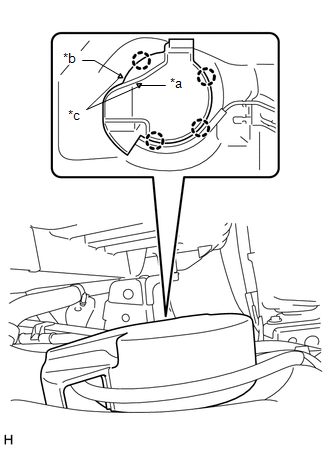
(b) Install the 2 fuel tank bands. (1) Install the 2 fuel tank bands with the 2 pins and 2 clips. (2) Install the 2 fuel tank bands with the 2 bolts. Torque: 62 N·m {632 kgf·cm, 46 ft·lbf} |
|
.png)
(c) Connect the 2 fuel suction tube with pump and gauge assembly connectors.
|
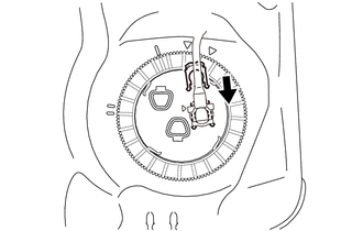
(d) w/ Fuel Tank Cover: (1) Engage the 4 claws and install the fuel tank cover. HINT: When installing, align the mark of the fuel tank cover with the mark of the fuel tank assembly as shown in the illustration. |
|
(e) Connect the fuel breather tube.
Click here
7. CONNECT FUEL TANK VENT HOSE SUB-ASSEMBLY
(a) Connect the fuel tank vent hose sub-assembly.
Click here
8. CONNECT FUEL TANK INLET PIPE SUB-ASSEMBLY
|
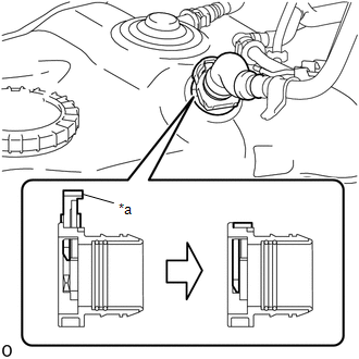
(a) Connect the fuel tank inlet pipe sub-assembly to the fuel tank assembly and lock it by pushing in the retainer of quick connector. NOTICE:
|
|
9. CONNECT FUEL TANK MAIN TUBE SUB-ASSEMBLY
(a) Connect the fuel tank main tube sub-assembly.
Click here
(b) Install the fuel pipe clamp.
10. INSTALL NO. 1 FUEL TANK PROTECTOR SUB-ASSEMBLY (for Hydraulic Brake Booster)
(a) Install the No. 1 fuel tank protector sub-assembly to the 2 fuel tank bands with the 4 nuts.
Torque:
20 N·m {204 kgf·cm, 15 ft·lbf}
11. ADD FUEL
12. CONNECT CABLE TO NEGATIVE BATTERY TERMINAL
Torque:
5.4 N·m {55 kgf·cm, 48 in·lbf}
NOTICE:
When disconnecting the cable, some systems need to be initialized after the cable is reconnected.
Click here
13. INSPECT FOR FUEL LEAK
Click here
 Removal
REMOVAL
PROCEDURE
1. PRECAUTION
NOTICE:
After turning the ignition switch off, waiting time may be required before disconnecting
the cable from the battery terminal. Therefore, make sure to read ...
 2gr-fks Ignition
...
Other materials:
Cruise Control Switch Circuit
DESCRIPTION
The cruise control main switch is used to turn the dynamic radar cruise control
system on and off, as well as operate 7 functions: SET, - (COAST), TAP-DOWN, RES
(RESUME), + (ACCEL), TAP-UP and CANCEL.
The SET, TAP-DOWN and - (COAST) functions, and the RES (RESUME), TAP-UP and +
( ...
Precaution
PRECAUTION
1. The type of ignition switch used on this model differs depending on the specifications
of the vehicle. The expressions listed in the table below are used in this section.
Expression
Ignition Switch (Position)
Engine Switch (Condition)
...
Problem Symptoms Table
PROBLEM SYMPTOMS TABLE
HINT:
The forward recognition camera is used by multiple systems. If any malfunctions
occur, refer to Problem Symptoms Table of each system.
Dynamic radar cruise control system (for 2GR-FKS): Click here
Dynamic radar cruise control syste ...
