Toyota Tacoma (2015-2018) Service Manual: Installation
INSTALLATION
CAUTION / NOTICE / HINT
CAUTION:
Some of these service operations affect the SRS airbag system. Read the precautionary
notices concerning the SRS airbag system before servicing (See page
.gif) ).
).
HINT:
- Use the same procedure for both the RH and LH sides.
- The procedure described below is for the LH side.
PROCEDURE
1. INSTALL FRONT AIRBAG SENSOR
(a) Check that the ignition switch is off.
(b) Check that the cable is disconnected from the negative (-) battery terminal.
CAUTION:
Wait at least 90 seconds after disconnecting the cable from the negative (-) battery terminal to disable the SRS system.
(c) Connect the connector to the front airbag sensor.
NOTICE:
When connecting any airbag connector, take care not to damage the airbag wire harness.
(1) Before connecting the connector, check that the position of the white housing lock is correct as shown in the illustration.
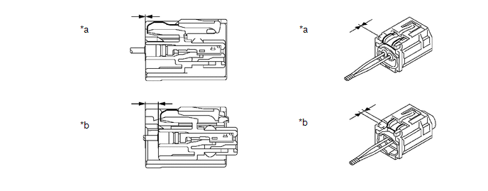
|
*a |
Incorrect |
*b |
Correct |
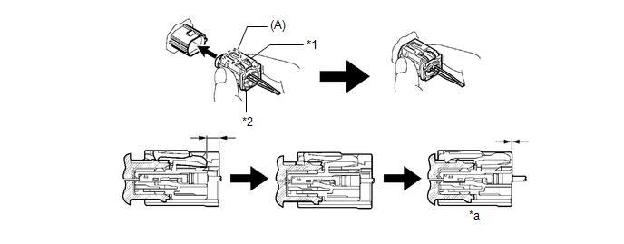
(2) Be sure to engage the connectors until they are locked (when locking, make sure that a click sound can be heard).
 Text in Illustration
|
*1 |
Housing Lock |
*2 |
CPA |
|
*a |
Connection is Completed |
- |
- |
HINT:
When engaged, the white housing lock will slide. Be sure not to hold the white housing lock and part (A), as it may result in an insecure fit.
(d) Engage the 2 claws into the body hole and install the front airbag sensor with the 2 bolts.
Torque:
9.0 N·m {92 kgf·cm, 80 in·lbf}
NOTICE:
- If the front airbag sensor has been dropped, or there are any cracks, dents or other defects in the case or connector, replace it with a new one.
- When installing the front airbag sensor, be careful that the SRS wiring does not interfere with or is not pinched between other parts.
- Make sure that the 2 claws (stopper) is securely inserted into the body hole.
- Tighten the bolt while holding the front airbag sensor because the front airbag sensor 2 claws (stopper) is easily damaged.
(e) Check that there is no looseness in the installation parts of the front airbag sensor.
2. INSTALL RADIATOR SIDE DEFLECTOR
3. INSTALL RADIATOR GRILLE
4. CONNECT CABLE TO NEGATIVE BATTERY TERMINAL
Torque:
5.4 N·m {55 kgf·cm, 48 in·lbf}
NOTICE:
When disconnecting the cable, some systems need to be initialized after the cable is reconnected.
Click here
5. INSPECT SRS WARNING LIGHT
Click here
 On-vehicle Inspection
ON-VEHICLE INSPECTION
CAUTION / NOTICE / HINT
CAUTION:
Be sure to correctly follow the removal and installation procedures for the front
airbag sensors.
PROCEDURE
1. INSPECT FRONT AIRBAG SENSOR ...
 Removal
REMOVAL
CAUTION / NOTICE / HINT
CAUTION:
Some of these service operations affect the SRS airbag system. Read the precautionary
notices concerning the SRS airbag system before servicing (See page
...
Other materials:
Removal
REMOVAL
PROCEDURE
1. REMOVE FRONT WIPER ARM HEAD CAP
(a) Using a screwdriver with its tip wrapped in protective tape, disengage
the 3 claws to remove the front wiper arm head cap.
Text in Illustration
*a
Protective Tape
HINT ...
Removal
REMOVAL
CAUTION / NOTICE / HINT
HINT:
Use the same procedure for the RH and LH sides.
The procedure listed below is for the LH side.
PROCEDURE
1. REMOVE REAR DOOR FRAME GARNISH
(See page )
2. REMOVE REAR DOOR INSIDE HANDLE BEZEL PLUG
(See page )
3. REMOVE REAR ARMREST ...
Transfer Case Front Oil Seal
Components
COMPONENTS
ILLUSTRATION
Replacement
REPLACEMENT
PROCEDURE
1. DRAIN TRANSFER OIL
2. SUPPORT TRANSMISSION ASSEMBLY
3. REMOVE NO. 3 FRAME CROSSMEMBER SUB-ASSEMBLY
4. REMOVE TRANSFER CASE LOWER PROTECTOR
5. REMOVE FRONT PROPELLER SHAFT ASSEMBLY
(See page )
6. ...
