Toyota Tacoma (2015-2018) Service Manual: Installation
INSTALLATION
PROCEDURE
1. INSTALL REAR SEAT 3 POINT TYPE OUTER BELT ASSEMBLY
|
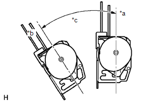
(a) Before installing the rear seat 3 point type outer belt assembly, check the ELR function. Text in Illustration
(1) When the inclination of the retractor is 15° or less, check that the belt can be pulled from the retractor. When the inclination of the retractor is over 45°, check that the belt locks. NOTICE: Do not disassemble the retractor. If operation is not as specified, replace the rear seat 3 point type outer belt assembly. |
|
|
(b) Engage the 2 guides to temporarily install the rear seat 3 point type outer belt assembly with the 2 bolts. |
|
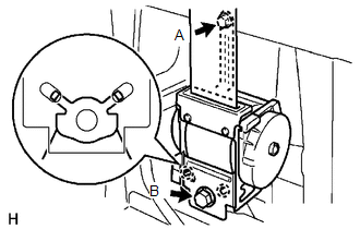
(c) Tighten bolt A, and then tighten bolt B.
Torque:
12.5 N·m {127 kgf·cm, 9 ft·lbf}
(for bolt A)
42 N·m {428 kgf·cm, 31 ft·lbf}
(for bolt B)
(d) Tighten the bolt to connect the shoulder anchor.
Torque:
42 N·m {428 kgf·cm, 31 ft·lbf}
(e) Check that the shoulder anchor rotates smoothly.
|
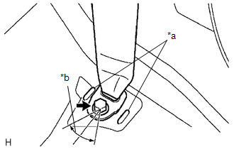
(f) Connect the floor anchor with the bolt. Text in Illustration
Torque: 42 N·m {428 kgf·cm, 31 ft·lbf} NOTICE:
|
|
(g) Check the ELR lock.
NOTICE:
The check should be performed with the rear seat 3 point type outer belt assembly installed.
(1) With the belt installed, check that the belt locks when it is pulled out quickly.
If the operation is not as specified, replace the rear seat 3 point type outer belt assembly.
(h) Remove the bolt to disconnect the floor anchor.
2. INSTALL QUARTER INSIDE TRIM BOARD
.gif)
3. CONNECT REAR SEAT 3 POINT TYPE OUTER BELT ASSEMBLY
4. INSTALL QUARTER TRIM LOWER PANEL
5. INSTALL LUGGAGE COMPARTMENT SIDE TRAY
6. CONNECT REAR DOOR OPENING TRIM WEATHERSTRIP
7. INSTALL REAR DOOR SCUFF PLATE
8. INSTALL REAR SEATBACK HINGE SUB-ASSEMBLY
9. INSTALL REAR SEATBACK ASSEMBLY
10. INSTALL REAR SEATBACK HINGE COVER
 Components
COMPONENTS
ILLUSTRATION
ILLUSTRATION
...
 Removal
REMOVAL
PROCEDURE
1. REMOVE REAR SEATBACK HINGE COVER
2. REMOVE REAR SEATBACK ASSEMBLY
3. REMOVE REAR SEATBACK HINGE SUB-ASSEMBLY
4. REMOVE REAR DOOR SCUFF PLATE
5. DISCONNECT REAR ...
Other materials:
Inspection
INSPECTION
PROCEDURE
1. INSPECT OIL CLEARANCE
(a) Using a micrometer and caliper gauge, measure the oil seal clearance.
Standard clearance:
0.021 to 0.043 mm (0.0008 to 0.0017 in.)
Maximum clearance:
0.07 mm (0.0028 in.)
If it is greater than the maximum, replace the vane pump assembly.
...
Terminals Of Ecm
TERMINALS OF ECM
HINT:
The standard normal voltage between each pair of ECM terminals is shown in the
table below. The appropriate conditions for checking each pair of terminals are
also indicated. The result of checks should be compared with the standard normal
voltage for that pair of te ...
Rear Door(for Double Cab)
Components
COMPONENTS
ILLUSTRATION
ILLUSTRATION
ILLUSTRATION
ILLUSTRATION
ILLUSTRATION
Adjustment
ADJUSTMENT
CAUTION / NOTICE / HINT
HINT:
Use the same procedures for both the LH and RH sides.
The procedure described below is for the LH side.
Centering bolts ...
