Toyota Tacoma (2015-2018) Service Manual: Installation
INSTALLATION
CAUTION / NOTICE / HINT
HINT:
- Use the same procedure for the RH side and LH side.
- The following procedure is for the LH side.
PROCEDURE
1. INSTALL FRONT DOOR GLASS OUTER WEATHERSTRIP ASSEMBLY
|
(a) Engage the 5 claws to install the front door glass outer weatherstrip assembly. |
|
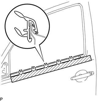
(b) Remove the protective tape.
2. INSTALL FRONT DOOR GLASS SUB-ASSEMBLY
Click here .gif)
3. INSTALL NO. 2 FRONT DOOR SERVICE HOLE COVER
Click here
4. INSTALL FRONT DOOR SERVICE HOLE COVER
Click here
5. INSTALL NO. 1 DOOR TRIM BRACKET
Click here
6. INSTALL FRONT DOOR INSIDE HANDLE SUB-ASSEMBLY
Click here
7. INSTALL OUTER REAR VIEW MIRROR ASSEMBLY
Click here
8. CONNECT CABLE TO NEGATIVE BATTERY TERMINAL
Torque:
5.4 N·m {55 kgf·cm, 48 in·lbf}
NOTICE:
When disconnecting the cable, some systems need to be initialized after the cable is reconnected.
Click here
9. INSPECT POWER WINDOW OPERATION
w/ Jam Protection Function:
Click here
w/o Jam Protection Function:
Click here
 Removal
REMOVAL
CAUTION / NOTICE / HINT
HINT:
Use the same procedure for the RH side and LH side.
The following procedure is for the LH side.
PROCEDURE
1. PRECAUTION
NOTICE:
After tur ...

Other materials:
Removal
REMOVAL
PROCEDURE
1. REMOVE REAR SEATBACK HINGE COVER
2. REMOVE REAR SEATBACK ASSEMBLY
3. REMOVE REAR SEATBACK HINGE SUB-ASSEMBLY
4. REMOVE REAR DOOR SCUFF PLATE
5. DISCONNECT REAR DOOR OPENING TRIM WEATHERSTRIP
(a) Disconnect the rear door opening trim weatherstrip to ...
Installation
INSTALLATION
CAUTION / NOTICE / HINT
HINT:
Perform "Inspection After Repairs" after replacing the fuel delivery pipe assembly
LH (fuel pressure sensor) (See page ).
PROCEDURE
1. INSTALL FUEL PIPE PLUG SUB-ASSEMBLY
(a) Install a new O-ring, new No. 1 fuel injector back-up ring, new ...
Problem Symptoms Table
PROBLEM SYMPTOMS TABLE
HINT:
Use the table below to help determine the cause of problem symptoms. If multiple
suspected areas are listed, the potential causes of the symptoms are listed in order
of probability in the "Suspected Area" column of the table. Check each symptom by
check ...
