Toyota Tacoma (2015-2018) Service Manual: Installation
INSTALLATION
CAUTION / NOTICE / HINT
HINT:
Perform "Inspection After Repairs" after replacing the fuel delivery pipe assembly
LH (fuel pressure sensor) (See page .gif) ).
).
PROCEDURE
1. INSTALL FUEL PIPE PLUG SUB-ASSEMBLY
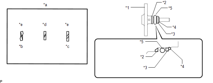
(a) Install a new O-ring, new No. 1 fuel injector back-up ring, new No. 2 fuel injector back-up ring and new No. 3 fuel injector back-up ring to the fuel pipe plug sub-assembly as shown in the illustration.
 Text in Illustration
|
*1 |
Fuel Pipe Plug Sub-assembly |
*2 |
No. 1 Fuel Injector Back-up Ring |
|
*3 |
No. 3 Fuel Injector Back-up Ring |
*4 |
No. 3 Fuel Injector Back-up Ring |
|
*5 |
O-ring |
- |
- |
|
*a |
Opening |
*b |
Overlapping |
|
*c |
Stretched |
*d |
Correct |
|
*e |
Incorrect |
- |
- |
NOTICE:
- Check that there is no foreign matter or damage on the O-ring groove of the fuel pipe plug sub-assembly.
- Check that the No. 1 fuel injector back-up ring and No. 3 fuel injector back-up ring are installed in the correct orientation.
- Make sure that the No. 1 fuel injector back-up ring, No. 2 fuel injector back-up ring, No. 3 fuel injector back-up ring and O-ring are installed in the correct order.
- Check that the alignment of the No. 1 fuel injector back-up ring is not overlapped or stretched as shown in the illustration.
- After installing the O-ring, check that it is not contaminated with foreign matter and is not damaged.
(b) Secure the fuel delivery pipe assembly LH in a vise between aluminum plates.
NOTICE:
Do not overtighten the vise.
|
(c) Install a new gasket to the fuel pipe plug sub-assembly as shown in the illustration. |
|
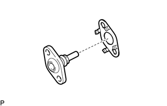
(d) Using a 5 mm hexagon wrench, install the fuel pipe plug sub-assembly to the fuel delivery pipe assembly LH with the 2 bolts.
Torque:
10 N·m {102 kgf·cm, 7 ft·lbf}
(e) Install a new dust cap sub-assembly to the fuel pipe plug sub-assembly.
2. INSTALL FUEL DELIVERY PIPE ASSEMBLY LH (FUEL PRESSURE SENSOR)
(See page )
NOTICE:
- Do not remove the fuel pressure sensor from the fuel delivery pipe sub-assembly LH.
- If a fuel pressure sensor is removed, replace the fuel delivery pipe sub-assembly LH (fuel pressure sensor) with a new one.
HINT:
Perform "Inspection After Repairs" after replacing the fuel delivery pipe assembly
LH (fuel pressure sensor) (See page ).
 Inspection
INSPECTION
PROCEDURE
1. INSPECT FUEL DELIVERY PIPE SUB-ASSEMBLY LH (FUEL PRESSURE SENSOR)
NOTICE:
Do not remove the fuel pressure sensor from the fuel delivery pipe sub-assembly
LH.
...
 Fuel Pump
...
Other materials:
Registered Device cannot be Deleted
PROCEDURE
1.
DELETE OPERATION
(a) Check if a registered portable player can be deleted normally.
OK:
Registered portable player can be deleted normally.
OK
END
NG
PROCEED TO NEXT SUSPECTED AREA SHOWN IN PROBLEM SYM ...
Key Reminder Buzzer does not Sound
DESCRIPTION
The key reminder warning buzzer sounds when the driver side door is opened while
the ignition switch is in the LOCK or ACC positions. The key reminder warning buzzer
is activated when the main body ECU (multiplex network body ECU) sends a key switch
signal and driver side courtesy ...
Blind Spot Monitor Main Switch
Components
COMPONENTS
ILLUSTRATION
Removal
REMOVAL
PROCEDURE
1. REMOVE INSTRUMENT PANEL LOWER CENTER FINISH PANEL
(See page )
2. REMOVE BLIND SPOT MONITOR MAIN SWITCH (WARNING CANCELING SWITCH ASSEMBLY)
(a) Disengage the 2 claws to remove the blind spot monitor main switch ...
