Toyota Tacoma (2015-2018) Service Manual: Installation
INSTALLATION
PROCEDURE
1. INSTALL PROPELLER SHAFT WITH CENTER BEARING ASSEMBLY
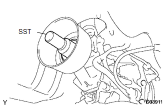
(a) Remove SST from the extension housing.
(b) Install the propeller shaft to the extension housing.
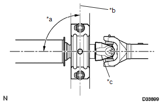
(c) Completely remove any oil or the like and clean the contact surfaces of the propeller shaft flange and differential flange.
|
(d) Align the matchmarks on the propeller shaft flange and differential flange. Text in Illustration
|
|
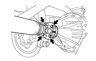
(e) for Differential Type BD20:
(1) Install the propeller shaft with the 4 bolts, 4 washers and 4 nuts.
Torque:
88 N·m {899 kgf·cm, 65 ft·lbf}
(f) for Differential Type BD22:
(1) Install the propeller shaft with the 4 washers and 4 nuts.
Torque:
88 N·m {899 kgf·cm, 65 ft·lbf}
|
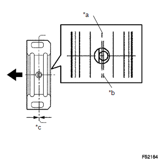
(g) Temporarily install the center No. 2 support bearing assembly with the 2 bolts. Text in Illustration
HINT: Make sure the bearing is installed with the drain hole facing downwards. |
|
|
(h) Adjust the center No. 2 support bearing assembly. Text in Illustration
HINT:
|
|
(i) Tighten the 2 bolts.
Torque:
36 N·m {369 kgf·cm, 27 ft·lbf}
2. INSPECT FOR TRANSMISSION OIL LEAK
 Inspection
INSPECTION
PROCEDURE
1. INSPECT PROPELLER SHAFT WITH CENTER BEARING ASSEMBLY
(a) Using a dial indicator, check the propeller shaft with center bearing assembly
runout.
Maximum runout:
0.6 mm ...
 Reassembly
REASSEMBLY
PROCEDURE
1. INSPECT CENTER NO. 2 SUPPORT BEARING ASSEMBLY
(a) When turning the center No. 2 support bearing assembly with your hand, check
that it turns smoothly without catching an ...
Other materials:
Head restraints
Head restraints are provided for all seats.
■ Adjusting the head restraints
Bench type front seat
Up
Pull the head restraints up.
Down
Push the head restraint down while pushing the lock release button.
Separated type front seat
Up
Pull the head restraints up.
Down
Push th ...
Front Radar Sensor Incorrect Axial Gap (C1A11)
DESCRIPTION
When the vehicle is determined to be driving in a straight line or on a gradual
curve based on signals from the yaw rate sensor, etc., the millimeter wave radar
sensor assembly performs self diagnosis to check if the sensor beam axis has deviated.
If the millimeter wave radar sens ...
Front Axle Hub Bolt
Installation
INSTALLATION
PROCEDURE
1. INSTALL FRONT AXLE HUB BOLT
(a) Install a new hub bolt through the axle hub.
(b) Install the washer plate, as shown in the illustration, through the hub bolt,
and install the hub bolt by tightening the hub nut.
2. INSTALL FRONT DISC
3. INSTALL FRON ...
