Toyota Tacoma (2015-2018) Service Manual: Installation
INSTALLATION
PROCEDURE
1. INSTALL FRONT DRIVE SHAFT
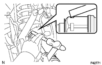
(a) Coat the spline of the inboard joint shaft with gear oil.
(b) Align the shaft splines and install the front drive shaft with a brass bar and hammer.
NOTICE:
- Set the snap ring with the opening side facing downward.
- Be careful not to damage the oil seal.
HINT:
Whether the inboard joint shaft is in contact with the pinion shaft or not can be confirmed from the sound or feeling when driving it.
2. INSTALL FRONT SUSPENSION LOWER ARM
(a) Install the front lower ball joint attachment with the 2 bolts.
Torque:
160 N·m {1631 kgf·cm, 118 ft·lbf}
3. INSTALL FRONT AXLE HUB NUT
(a) Install the front axle hub nut.
Torque:
235 N·m {2396 kgf·cm, 173 ft·lbf}
(b) Install the adjusting cap and a new cotter pin.
(c) Install the front axle hub grease cap.
4. INSTALL TIE ROD END SUB-ASSEMBLY
(a) Install the tie rod end sub-assembly to the steering knuckle.
(b) Install the nut.
Torque:
91 N·m {928 kgf·cm, 67 ft·lbf}
(c) Install a new cotter pin.
5. INSTALL FRONT SPEED SENSOR
(a) Install the speed sensor wire harness to the steering knuckle with the bolt.
Torque:
13 N·m {133 kgf·cm, 10 ft·lbf}
(b) Engage the 2 clamps.
(c) Install the front speed sensor with the bolt.
Torque:
8.3 N·m {85 kgf·cm, 73 in·lbf}
6. INSTALL FRONT WHEEL
Torque:
113 N·m {1152 kgf·cm, 83 ft·lbf}
7. ADD DIFFERENTIAL OIL
.gif)
8. INSPECT DIFFERENTIAL OIL
9. INSPECT SPEED SENSOR SIGNAL (for Hydraulic Brake Booster)
(See page )
10. INSPECT SPEED SENSOR SIGNAL (for Vacuum Brake Booster)
(See page )
11. INSPECT FOR DIFFERENTIAL OIL LEAK
12. INSPECT AND ADJUST FRONT WHEEL ALIGNMENT
(See page )
 Removal
REMOVAL
PROCEDURE
1. REMOVE FRONT WHEEL
2. DRAIN DIFFERENTIAL OIL
3. SEPARATE FRONT SPEED SENSOR
(a) Remove the bolt and separate the front speed sensor.
(b) Disengage the 2 clamps.
(c) Remov ...
 Propeller Shaft
...
Other materials:
Disposal
DISPOSAL
CAUTION / NOTICE / HINT
CAUTION:
Before performing pre-disposal deployment of any SRS part, review and closely
follow all applicable environmental and hazardous material regulations. Predisposal
deployment may be considered hazardous material treatment.
PROCEDURE
1. PRECAUTION
...
Removal
REMOVAL
PROCEDURE
1. REMOVE TRANSMISSION INSULATOR RH (for 2GR-FKS)
2. REMOVE TRANSMISSION INSULATOR RH (for 2TR-FE)
3. SEPARATE WATER BY-PASS PIPE (for 2GR-FKS)
(a) Remove the 2 bolts to separate the water by-pass pipe from the automatic
transmission assembly.
...
Vehicle Speed Sensor Circuit (C1AA3)
DESCRIPTION
The forward recognition camera receives vehicle speed signals from the skid control
ECU. If the skid control ECU receives a vehicle speed sensor malfunction signal,
it informs the forward recognition camera via CAN communication, and DTC C1AA3 is
stored.
DTC No.
...
