Toyota Tacoma (2015-2018) Service Manual: Inspection
INSPECTION
PROCEDURE
1. INSPECT WINDSHIELD WIPER MOTOR ASSEMBLY
(a) Check the LO operation.
Text in Illustration|
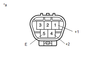
*a |
Component without harness connected (Windshield Wiper Motor Assembly) |
(1) Apply battery voltage to the windshield wiper motor connector and check the speed of the windshield wiper motor assembly.
OK:
|
Measurement Condition |
Specified Condition |
|---|---|
|
Battery positive (+) → Terminal 1 (+1) Battery negative (-) → Terminal 5 (E) |
Motor operates at low speed |
If the result is not as specified, replace the windshield wiper motor assembly.
(b) Check the HI operation.
(1) Apply battery voltage to the windshield wiper motor connector and check the speed of the windshield wiper motor assembly.
OK:
|
Measurement Condition |
Specified Condition |
|---|---|
|
Battery positive (+) → Terminal 4 (+2) Battery negative (-) → Terminal 5 (E) |
Motor operates at high speed |
If the result is not as specified, replace the windshield wiper motor assembly.
 On-vehicle Inspection
ON-VEHICLE INSPECTION
PROCEDURE
1. INSPECT FRONT WIPER MOTOR (for Driver Side)
Text in Illustration
*a
Matchmark
(a) Check the stop (park) position.
(b) Operate t ...
 Installation
INSTALLATION
PROCEDURE
1. INSTALL WINDSHIELD WIPER MOTOR ASSEMBLY
(a) Apply MP grease to the crank arm pivot of the windshield wiper motor
assembly.
Text in Illustration
...
Other materials:
Open in Bus 5 Main Bus Line
DESCRIPTION
There may be an open circuit in one of the CAN main bus lines when the resistance
between terminals 15 (CA5H) and 16 (CA5L) of the central gateway ECU (network gateway
ECU) is 70 Ω or higher.
Detection Item
Trouble Area
Resistance between ter ...
Reassembly
REASSEMBLY
PROCEDURE
1. INSTALL MASTER CYLINDER RESERVOIR GROMMET
(a) Apply lithium soap base glycol grease to 2 new grommets.
(b) Install the 2 grommets onto the brake master cylinder reservoir.
2. INSTALL BRAKE MASTER CYLINDER RESERVOIR ASSEMBLY
(a) Install the brake master cylinder reservoi ...
Reassembly
REASSEMBLY
PROCEDURE
1. INSTALL REAR BUMPER SIDE STAY LH
(a) Install the rear bumper side stay LH with the 2 bolts.
Torque:
30 N·m {306 kgf·cm, 22 ft·lbf}
2. INSTALL REAR BUMPER SIDE STAY RH
HINT:
Use the same procedure as for ...
