Toyota Tacoma (2015-2018) Service Manual: Illumination for Panel Switch does not Come on with Tail Switch ON
PROCEDURE
|
1. |
CHECK VEHICLE SIGNAL (OPERATION CHECK) |
(a) Enter the "Vehicle Signal Check Mode" screen. Refer to Check Vehicle Signal
in Operation Check (See page .gif) ).
).
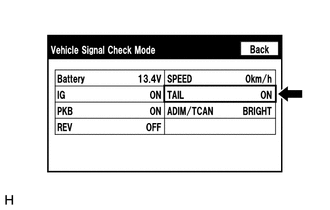
(b) Check that the display changes between ON and OFF according to the light control switch operation.
OK:
|
Light Control Switch |
Display |
|---|---|
|
Tail or head |
ON |
|
Off |
OFF |
HINT:
This display is updated once per second. As a result, it is normal for the display to lag behind the actual switch operation.
| OK | .gif) |
REPLACE RADIO AND DISPLAY RECEIVER ASSEMBLY |
| NG | |
PROCEED TO NEXT SUSPECTED AREA SHOWN IN PROBLEM SYMPTOMS TABLE |
 Radio Broadcast cannot be Received or Poor Reception
PROCEDURE
1.
CHECK RADIO AND DISPLAY RECEIVER ASSEMBLY
(a) Check the radio automatic station search function.
(1) Check the radio automatic station search function b ...
 Display does not Dim when Light Control Switch is Turned ON
PROCEDURE
1.
CHECK IMAGE QUALITY SETTING
(a) Display the "Display" screen.
(b) Turn the light control switch to the tail or head position.
(c) Check if &q ...
Other materials:
Steering Lock Position Signal Circuit Malfunction (B2285)
DESCRIPTION
This DTC is stored when the steering lock position signal sent by the steering
lock ECU (steering lock actuator or upr bracket assembly) via direct line and the
steering lock position signal sent via LIN communication do not match.
HINT:
When the cable is disconnected and reconnec ...
Data List / Active Test
DATA LIST / ACTIVE TEST
1. READ DATA LIST
HINT:
Using the Techstream to read the Data List allows the values or states of switches,
sensors, actuators and other items to be read without removing any parts. This non-intrusive
inspection can be very useful because intermittent conditions or sig ...
Terminals Of Ecu
TERMINALS OF ECU
1. TERMINAL INSPECTION
Text in Illustration
*a
Component without harness connected
(Steering Lock ECU (Steering Lock Actuator or UPR Bracket Assembly))
-
-
(a) Measure the voltage and resistance according to the value(s) i ...
