Toyota Tacoma (2015-2018) Service Manual: Hydraulic Test
HYDRAULIC TEST
1. PERFORM HYDRAULIC TEST
(a) Measure the line pressure.
CAUTION:
The line pressure test should always be performed with at least 2 people. One person should observe the condition of the wheels and wheel chocks while the other is performing the test.
NOTICE:
- Perform the test while the ATF (Automatic Transmission Fluid) temperature is between 50 and 80°C (122 and 176°F).
- Be careful to prevent the hose of SST from interfering with the exhaust pipe.
- This check must be conducted after checking and adjusting the engine.
- Perform the test with the air conditioning off.
- When conducting stall test, do not continue for more than 5 seconds.
- When performing the stall speed test more than once, make sure to wait 15 seconds or more between tests.
(1) Warm up the ATF (Automatic Transmission Fluid).
(2) Turn the ignition switch off.
(3) Lift the vehicle up.
(4) Remove the test plug from the transmission case and connect SST.
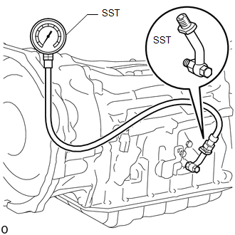
SST: 09993-19015
09993-00010
09993-00040
(5) Lower the vehicle.
(6) Fully apply the parking brake and chock the 4 wheels.
(7) Start the engine and check the idling speed.
(8) Keep your left foot pressed firmly on the brake pedal and move the shift lever to D.
(9) Fully depress the accelerator pedal with your right foot. Quickly read the highest line pressure when the engine speed reaches the stall speed.
(10) In the same manner, perform the test with the shift lever in R.
Specified Line Pressure|
Condition |
D Position |
R Position |
|---|---|---|
|
Stall speed |
1450 to 1740 kPa (14.8 to 17.7 kgf/cm2, 210 to 252 psi) |
1550 to 1840 kPa (15.8 to 18.8 kgf/cm2, 225 to 267 psi) |
|
Problem |
Possible Cause |
|---|---|
|
Measured values are higher than the specified value in all positions |
|
|
Measured values are lower than the specified value in all positions |
|
|
Pressure is low in D position only |
|
|
Pressure is low in R position only |
|
 System Diagram
SYSTEM DIAGRAM
The configuration of the electronic control system in the AC60E automatic transmission
is as shown in the following chart.
...
 Mechanical System Tests
MECHANICAL SYSTEM TESTS
1. STALL SPEED TEST
HINT:
This test is to check the overall performance of the engine and transmission.
CAUTION:
This test should be done on a paved surface (a sur ...
Other materials:
Removal
REMOVAL
PROCEDURE
1. REMOVE INSTRUMENT PANEL LOWER FINISH PANEL SUB-ASSEMBLY
(See page )
2. REMOVE DRIVER SIDE JUNCTION BLOCK
(a) Disconnect the 5 connectors on the front side.
(b) Remove the 2 nuts to separate the driver side j ...
System Description
SYSTEM DESCRIPTION
1. GENERAL
(a) The air conditioning system has the following controls.
Control
Outline
Neural Network Control
This control is capable of effecting complex control by artificially
simulating the information processing method ...
Inspection
INSPECTION
PROCEDURE
1. INSPECT FUEL PUMP
(a) Inspect the resistance of the fuel pump.
(1) Measure the resistance according to the value(s) in the table below.
Text in Illustration
*a
Component without harness connected
(Fuel Pump)
...
