Toyota Tacoma (2015-2018) Service Manual: AUTO LSD Indicator Light Remains ON
DESCRIPTION
During normal mode, pressing the VSC OFF switch for a short amount of time changes vehicle to AUTO LSD mode.
WIRING DIAGRAM
.png)
CAUTION / NOTICE / HINT
NOTICE:
When replacing the brake actuator assembly, perform calibration (See page
.gif) ).
).
PROCEDURE
|
1. |
CHECK CAN COMMUNICATION LINE |
(a) Turn the ignition switch off.
(b) Connect the Techstream to the DLC3.
(c) Turn the ignition switch to ON.
(d) Turn the Techstream on.
(e) Select CAN Bus Check from the System Selection Menu screen and follow the
prompts on the screen to inspect the CAN bus (See page
).
OK:
CAN Bus Check indicates no malfunctions in CAN communication.
| NG | .gif) |
GO TO CAN COMMUNICATION SYSTEM (HOW TO PROCEED WITH TROUBLESHOOTING) |
|
.gif)
|
2. |
PERFORM ACTIVE TEST USING TECHSTREAM (Indicat. Auto LSD) |
(a) Turn the ignition switch off.
(b) Connect the Techstream to the DLC3.
(c) Turn the ignition switch to ON.
(d) Turn the Techstream on.
(e) Enter the following menus: Body Electrical / Combination Meter / Active Test.
(f) According to the display on the Techstream, perform the Active Test.
Combination Meter|
Tester Display |
Test Part |
Control Range |
Diagnostic Note |
|---|---|---|---|
|
Indicat. Auto LSD |
AUTO LSD indicator light |
OFF/ON |
Perform the test with the vehicle stopped and the engine idling |
(g) Check that the AUTO LSD indicator light on the combination meter assembly turns on or off in accordance with the Techstream operation.
OK:
The AUTO LSD indicator light turns on or off in accordance with the Techstream operation.
| NG | |
GO TO METER / GAUGE SYSTEM (HOW TO PROCEED WITH TROUBLESHOOTING) |
|
|
3. |
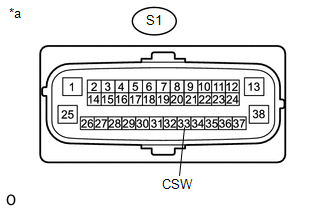
CHECK HARNESS AND CONNECTOR (CSW TERMINAL) |
(a) Disconnect the S1 skid control ECU connector.
|
(b) Measure the resistance according to the value(s) in the table below. Standard Resistance:
|
|
(c) Reconnect the S1 skid control ECU connector.
| OK | |
REPLACE BRAKE ACTUATOR ASSEMBLY |
|
|
4. |
INSPECT VSC OFF SWITCH |
(a) Turn the ignition switch off.
(b) Remove the VSC OFF switch (See page ).
(c) Inspect the VSC OFF switch (See page ).
OK:
The VSC OFF switch operates normally.
| OK | |
REPAIR OR REPLACE HARNESS OR CONNECTOR |
| NG | |
REPLACE VSC OFF SWITCH |
 AUTO LSD Indicator Light does not Come ON
DESCRIPTION
The AUTO LSD does not operate even if the VSC OFF switch is pressed under the
following conditions:
The brake system is faulty.
The temperature inside the hydraulic brake bo ...
 Slip Indicator Light does not Come ON
DESCRIPTION
Refer to Slip Indicator Light Remains ON (See page
).
WIRING DIAGRAM
Refer to Slip Indicator Light Remains ON (See page
).
CAUTION / NOTICE / HINT
NOTICE:
When replacing the skid ...
Other materials:
Inspection
INSPECTION
PROCEDURE
1. INSPECT TIRES
(a) Check the tires for wear and proper inflation pressure.
Standard Cold Tire Inflation Pressure:
Tire Size
Front Wheel
kPa (kgf/cm2, psi)
Rear Wheel
kPa (kgf/cm2, psi)
Spare Wheel
kPa (kgf/cm2, psi)
...
On-vehicle Inspection
ON-VEHICLE INSPECTION
PROCEDURE
1. INSPECT SHIFT LEVER POSITION
(a) When moving the shift lever from P to each position with the ignition switch
ON and the brake pedal depressed, check that the shift lever moves smoothly and
correctly into position.
(b) Start the engine and check that the ve ...
Installation
INSTALLATION
PROCEDURE
1. REMOVE MONOLITHIC CONVERTER PROTECTOR
(a) Install the upper monolithic converter protector and lower monolithic converter
protector with the 2 bolts and 2 nuts.
Torque:
11 N·m {107 kgf·cm, 8 ft·lbf}
(b) Install the clamp with the bolt as shown in the ...
