Toyota Tacoma (2015-2018) Service Manual: High Pitched Horn
Components
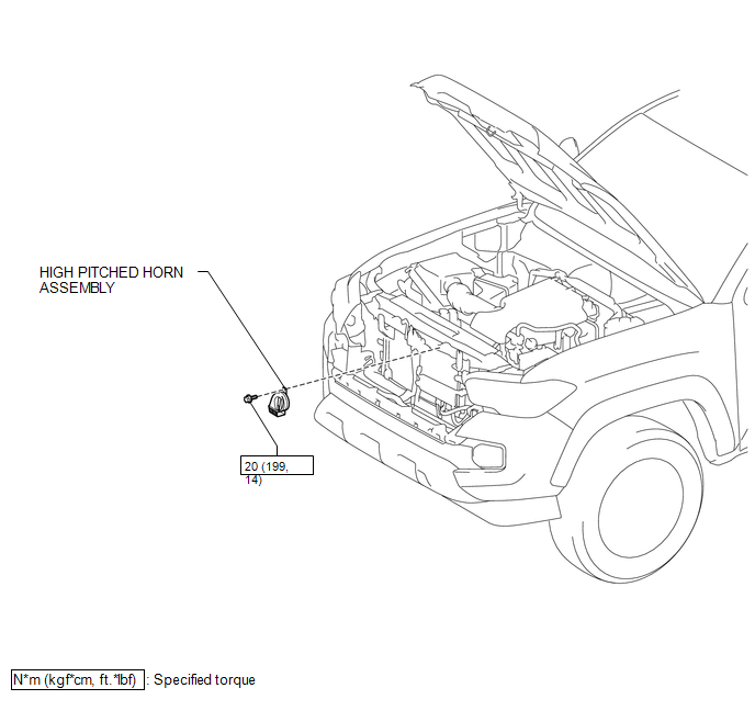
COMPONENTS
ILLUSTRATION
Removal
REMOVAL
PROCEDURE
1. REMOVE RADIATOR GRILLE
Click here .gif)
2. REMOVE HIGH PITCHED HORN ASSEMBLY
|
(a) Disconnect the connector. |
|
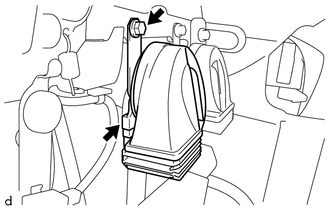
(b) Remove the bolt and high pitched horn assembly.
Inspection
INSPECTION
PROCEDURE
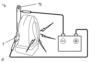
1. INSPECT HIGH PITCHED HORN ASSEMBLY
(a) Check the operation.
|
(1) Apply battery voltage to the terminal 1 and body ground, and check that the high pitched horn assembly sounds. Text in Illustration
OK:
If the result is not as specified, replace the high pitched horn assembly. |
|
Installation
INSTALLATION
PROCEDURE
1. INSTALL HIGH PITCHED HORN ASSEMBLY
(a) Install the high pitched horn assembly with the bolt.
Torque:
20 N·m {199 kgf·cm, 14 ft·lbf}
(b) Connect the connector.
2. INSTALL RADIATOR GRILLE
Click here .gif)
 Horn
Horn
...
 Horn Relay
On-vehicle Inspection
ON-VEHICLE INSPECTION
PROCEDURE
1. INSPECT HORN RELAY ASSEMBLY
(a) Check the resistance.
(1) Measure the resistance according to the value(s) in the table below ...
Other materials:
Playing an audio CD and MP3/WMA/AAC discs
Insert disc or select “CD” on the “Select Audio Source” screen to begin listening
to a CD.
Audio control screen
1. “Select Audio Source” screen appears
2. Audio CD
Displaying the track list
MP3/WMA/AAC
Displaying the folder list
3. Random playback
4. Repeat play
5. Pause
...
Precaution
PRECAUTION
1. BASIC REPAIR HINT
(a) HINTS ON OPERATIONS
1
Attire
Always wear a clean uniform.
A hat and safety shoes must be worn.
2
Vehicle protection
Prepare a grille cover, fe ...
Torque Converter Clutch Circuit Short to Battery or Open (P074015)
DESCRIPTION
Shift solenoid valve SL is turned on and off by signals from the ECM to control
the hydraulic pressure acting on the lock-up relay valve, which then controls operation
of the lock-up clutch.
DTC No.
DTC Detection Condition
Trouble Area
SA ...
