Toyota Tacoma (2015-2018) Service Manual: Washer Level Warning Switch
Components
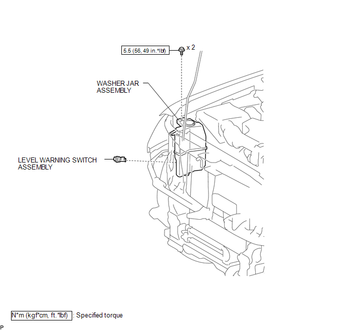
COMPONENTS
ILLUSTRATION
Inspection
INSPECTION
PROCEDURE
1. INSPECT LEVEL WARNING SWITCH ASSEMBLY
HINT:
This check should be performed with the windshield washer motor and pump assembly installed on the washer jar.
(a) Fill the washer jar with washer fluid.
|
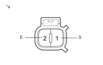
(b) Measure the resistance according to the value(s) in the table below. Standard Resistance:
HINT: *: The level warning switch assembly begins operating when the fluid volume is 600 to 800 cc (36.6 to 48.8 cu.in.) depending on the vehicle condition. Text in Illustration
If the result is not as specified, replace the level warning switch assembly. |
|
Installation
INSTALLATION
PROCEDURE
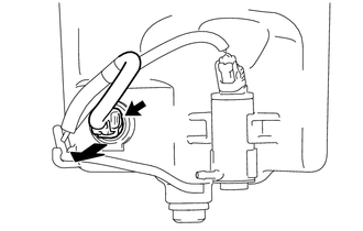
1. INSTALL LEVEL WARNING SWITCH ASSEMBLY
|
(a) Install the level warning switch assembly. |
|
(b) Connect the connector.
(c) Connect the washer hose to the windshield washer motor and pump assembly.
2. INSTALL WASHER JAR ASSEMBLY
.gif)
3. ADD WASHER FLUID
4. INSTALL HEADLIGHT ASSEMBLY RH
HINT:
Use the same procedure as for the LH side. (See page
)
Removal
REMOVAL
PROCEDURE
1. REMOVE HEADLIGHT ASSEMBLY RH
HINT:
Use the same procedure as for the LH side. (See page
.gif) )
)
2. SEPARATE WASHER JAR ASSEMBLY
3. DRAIN WINDSHIELD WASHER FLUID
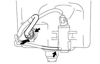
4. REMOVE LEVEL WARNING SWITCH ASSEMBLY
|
(a) Disconnect the connector. |
|
(b) Remove the level warning switch assembly as shown in the illustration.
 Front Wiper Rubber
Components
COMPONENTS
ILLUSTRATION
Installation
INSTALLATION
PROCEDURE
1. INSTALL FRONT WIPER RUBBER
(a) Install the 2 wiper rubber backing plates to the front wiper rubber.
...
 Washer Motor
Components
COMPONENTS
ILLUSTRATION
On-vehicle Inspection
ON-VEHICLE INSPECTION
PROCEDURE
1. INSPECT WINDSHIELD WASHER MOTOR AND PUMP ASSEMBLY
HINT:
This check should be performed with th ...
Other materials:
System Description
SYSTEM DESCRIPTION
1. GENERAL
(a) This system uses ultrasonic sensors to detect any obstacles at the corners
and the rear of the vehicle. The system then informs the driver of the distance
between the sensors and an obstacle as well as their positions by indicating them
on the multi-informat ...
Inspection
INSPECTION
PROCEDURE
1. INSPECT FUEL INJECTOR ASSEMBLY
(a) Measure the resistance according to the value(s) in the table below.
Standard Resistance:
Tester Connection
Condition
Specified Condition
1 - 2
20°C (68°F)
11.6 ...
Software Incompatibility with Body Control Module "B" (U1331)
DESCRIPTION
This DTC is stored when the destination information of the main body ECU (multiplex
network body ECU) does not match that of the blind spot monitor sensors.
DTC Code
DTC Detection Condition
Trouble Area
U1331
Destination in ...
