Toyota Tacoma (2005–2015) Owners Manual: Headlight switch
The headlights can be operated manually.
Turning the end of the lever turns on the lights as follows:
 Type A
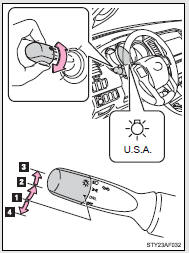
 The daytime running lights turn
on.
The daytime running lights turn
on.
 The side marker, parking, tail,
license plate, daytime running lights and instrument panel lights turn on.
The side marker, parking, tail,
license plate, daytime running lights and instrument panel lights turn on.
 The headlights and all lights listed
above (except daytime running lights) turn on.
The headlights and all lights listed
above (except daytime running lights) turn on.
 The daytime running lights turn
off.
The daytime running lights turn
off.
 Type B
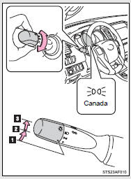
 The daytime running lights turn
on.
The daytime running lights turn
on.
 The side marker, parking, tail,
license plate, daytime running lights and instrument panel lights turn on.
The side marker, parking, tail,
license plate, daytime running lights and instrument panel lights turn on.
 The headlights and all lights listed
above (except daytime running lights) turn on.
The headlights and all lights listed
above (except daytime running lights) turn on.
Turning on the high beam headlights
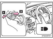
 With the headlights on, push the
lever forward to turn on the high beams.
With the headlights on, push the
lever forward to turn on the high beams.
Pull the lever back to the center position to turn the high beams off.
 Pull the lever toward you to turn
on the high beams.
Pull the lever toward you to turn
on the high beams.
Release the lever to turn them off.
You can flash the high beams with the headlights on or off.
■Daytime running light system
●To make your vehicle more visible to other drivers, the front turn signal lights turn on automatically whenever the engine is started and the parking brake is released. Daytime running lights are not designed for use at night.
Type A: Daytime running lights can be turned off by operating the switch.
●Compared to turning on the headlights, the daytime running light system offers greater durability and consumes less electricity, so it can help improve fuel economy.
■Automatic light off system
Opening the driver’s door with the engine switch in the ACC or LOCK position will turn the headlights and tail lights off.
To turn the lights on again, turn the engine switch to the ON position, or turn
the headlight switch off once and then back to the
 or
or
 position.
NOTICE
■To prevent battery discharge
Do not leave the lights on longer than necessary when the engine is not running.

 Fog light switch
The fog lights improve visibility in difficult driving conditions, such as
in rain or fog.
■The fog lights can be turned on only when
The headlights are on low beam. ...
Other materials:
Acceleration Sensor Stuck Malfunction (C1232,C1243,C1245)
DESCRIPTION
The skid control ECU (brake actuator assembly) receives signals from the yaw
rate and acceleration sensor (airbag sensor assembly) via the CAN communication
system.
The airbag sensor assembly has a built-in acceleration sensor and detects the
vehicle condition.
If there is troub ...
Components
COMPONENTS
ILLUSTRATION
*A
w/ Fuel Tank Cover
*B
for Hydraulic Brake Booster
*1
FUEL TANK ASSEMBLY
*2
FUEL TANK INLET PIPE SUB-ASSEMBLY
*3
FUEL TANK VENT HOSE SUB-ASSEMBLY
...
Reassembly
REASSEMBLY
PROCEDURE
1. INSTALL REAR BUMPER SIDE STAY LH
(a) Install the rear bumper side stay LH with the 2 bolts.
Torque:
30 N·m {306 kgf·cm, 22 ft·lbf}
2. INSTALL REAR BUMPER SIDE STAY RH
HINT:
Use the same procedure as for ...
