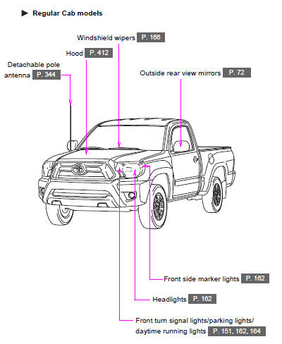
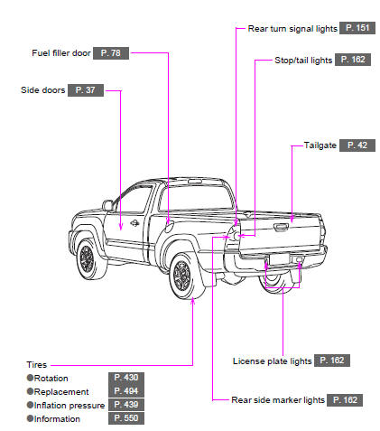
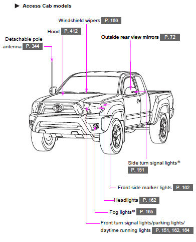
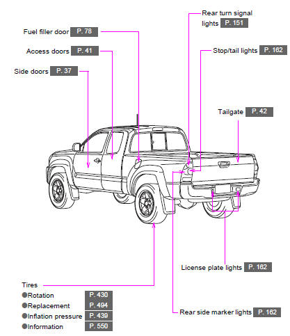
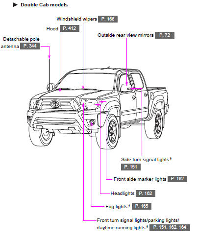
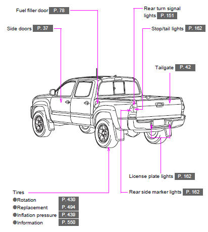
Toyota Tacoma (2005–2015) Owners Manual: Exterior

 Interior
*1: If equipped
* 2: Access Cab and Double Cab models
*3: Vehicles with auto anti- glare inside rear view mirror
*1: If equipped
*2: Vehicles with an automatic transmission
* : If equ ...
Other materials:
Destination Information Undefined (C1AB8)
DESCRIPTION
This DTC is stored when correct destination information is not sent from the
main body ECU (multiplex network body ECU) and destination information cannot be
confirmed after a blind spot monitor has been replaced.
DTC Code
DTC Detection Condition
Tr ...
Removal
REMOVAL
PROCEDURE
1. REMOVE FRONT FENDER MUDGUARD (w/ Mudguard)
Click here
2. REMOVE FRONT FENDER WHEEL OPENING MOULDING (w/ Over Fender)
Click here
3. REMOVE FRONT NO. 1 WHEEL OPENING EXTENSION PAD (w/ Front Spoiler)
(a) Remove 9 screws and front No. 1 wheel opening extension ...
Pressure Control Solenoid "B" Electrical (Shift Solenoid Valve SL2) (P0778)
DESCRIPTION
Changing from 1st to 6th is performed by the ECM turning shift solenoid valves
SL1, SL2, SL3 and SL4 on and off. If an open or short circuit occurs in any of the
shift solenoid valves, the ECM controls the remaining normal shift solenoid valves
to allow the vehicle to be operated ...
