Toyota Tacoma (2015-2018) Service Manual: Downhill Assist Control Switch Malfunction (Test Mode DTC) (C1379)
DESCRIPTION
DTC C1379 is cleared when the crawl control switch sends a crawl control operation signal or when test mode ends.
|
DTC Code |
DTC Detection Condition |
Trouble Area |
|---|---|---|
|
C1379 |
Stored only during test mode. |
|
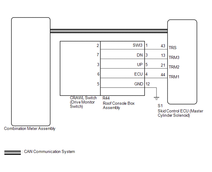
WIRING DIAGRAM
CAUTION / NOTICE / HINT
NOTICE:
- When replacing the skid control ECU (master cylinder solenoid), perform
calibration (See page
.gif) ).
). - Inspect the fuses for circuits related to this system before performing the following inspection procedure.
PROCEDURE
|
1. |
READ VALUE USING TECHSTREAM (CRAWL CONTROL SWITCH) |
(a) Turn the ignition switch off.
(b) Connect the Techstream to the DLC3.
(c) Turn the ignition switch to ON.
(d) Turn the Techstream on.
(e) Enter the following menus: Chassis / ABS/VSC/TRAC / Data List.
(f) Check the Data List for proper functioning of the crawl control switch.
ABS/VSC/TRAC|
Tester Display |
Measurement Item/Range |
Normal Condition |
Diagnostic Note |
|---|---|---|---|
|
Crawl Control Switch |
Crawl speed selector switch status/ LOW, MIDLOW, MID, MIDHIGH or HIGH |
Actual crawl speed selector switch position |
- |
OK:
The Techstream displays according to crawl control switch operation.
| NG | .gif) |
GO TO STEP 3 |
|
.gif)
|
2. |
CHECK TEST MODE DTC |
(a) Perform the crawl control switch check in the Test Mode Procedure (See page
).
OK:
Test mode DTC C1379 is cleared.
| OK | |
USE SIMULATION METHOD TO CHECK |
| NG | |
REPLACE MASTER CYLINDER SOLENOID |
|
3. |
INSPECT DRIVE MONITOR SWITCH |
(a) Remove the crawl control switch (drive monitor switch) (See page
).
(b) Inspect the crawl control switch (drive monitor switch) (See page
).
| NG | |
REPLACE DRIVE MONITOR SWITCH |
|
|
4. |
INSPECT ROOF CONSOLE BOX ASSEMBLY |
(a) Remove the roof console box assembly.
- for Double Cab: (See page
)
- for Access Cab: (See page
)
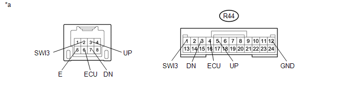 Text in Illustration
|
*a |
Component without harness connected (Roof Console Box Assembly) |
- |
- |
(b) Measure the resistance according the value(s) in the table below.
Standard Resistance:
|
Tester Connection |
Condition |
Specified Condition |
|---|---|---|
|
R44-1 (SWI3) - 2 |
Always |
Below 1 Ω |
|
R44-3 (DN) - 7 |
Always |
Below 1 Ω |
|
R44-4 (ECU) - 6 |
Always |
Below 1 Ω |
|
R44-5 (UP) - 3 |
Always |
Below 1 Ω |
|
R44-12 (GND) - 5 |
Always |
Below 1 Ω |
|
Result |
Proceed to |
|---|---|
|
OK |
A |
|
NG (for Double Cab) |
B |
|
NG (for Access Cab) |
C |
| A | |
REPAIR OR REPLACE HARNESS OR CONNECTOR (MASTER CYLINDER SOLENOID - ROOF CONSOLE BOX ASSEMBLY) |
| B | |
REPLACE ROOF CONSOLE BOX ASSEMBLY |
| C | |
REPLACE ROOF CONSOLE BOX ASSEMBLY |
 Diameter of the Tire is not Uniform (C1337)
DESCRIPTION
The skid control ECU (master cylinder solenoid) measures the speed of each wheel
by receiving signals from the speed sensors. These signals are used for recognizing
whether all 4 whee ...
 Acceleration Sensor Power Supply Voltage Malfunction (C1381)
DESCRIPTION
The skid control ECU (master cylinder solenoid) receives signals from the yaw
rate and acceleration (airbag sensor assembly) via the CAN communication system.
The airbag sensor assembl ...
Other materials:
Multi-terrain Select Indicator Light Remains ON
DESCRIPTION
Refer to Multi-terrain Select Indicator Light does not Come ON (See page
).
WIRING DIAGRAM
CAUTION / NOTICE / HINT
NOTICE:
When replacing the skid control ECU (master cylinder solenoid), perform
calibration (See page
).
Inspect the fuses for circuits related ...
Vehicle Speed Signal Malfunction (B2282,B2283)
DESCRIPTION
DTC B2282 is stored when the vehicle speed signal sent by the combination meter
assembly via direct line and the vehicle speed signal sent via CAN communication
do not match.
DTC B2283 is stored when a malfunction in the vehicle speed sensor is detected.
HINT:
When the cable is d ...
Steering Angle Sensor Initialization Incomplete (C1439,C1445)
DESCRIPTION
The skid control ECU (master cylinder solenoid) acquires steering angle sensor
(spiral cable with sensor sub-assembly) zero point every time the ignition switch
is turned to ON and the vehicle is driven at 35 km/h (22 mph) or more for approximately
5 seconds. The ECU also stores t ...
