Toyota Tacoma (2015-2018) Service Manual: Disassembly
DISASSEMBLY
CAUTION / NOTICE / HINT
HINT:
The procedure described below is for the LH side. Use the same procedure for both the LH and RH sides, unless otherwise specified.
PROCEDURE
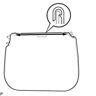
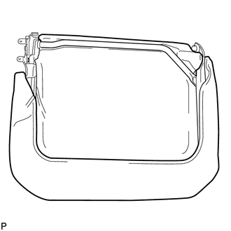
1. REMOVE REAR SEATBACK COVER
|
(a) Remove the 2 screws. |
|
(b) Disengage the 2 claws and remove the rear seatback cover.
2. REMOVE REAR SEATBACK LOCK COVER
|
(a) Remove the 2 screws and rear seatback lock cover. |
|
3. REMOVE REAR SEAT CUSHION UNDER COVER
|
(a) Remove the screw and rear seat cushion under cover. |
|
4. REMOVE REAR SEAT CUSHION COVER
|
(a) Remove the screw and rear seat cushion cover. |
|
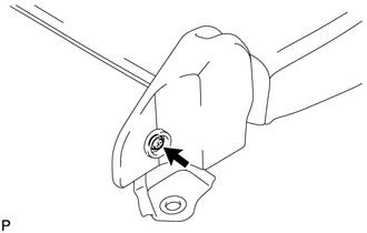
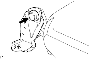
5. REMOVE REAR SEAT HINGE SUB-ASSEMBLY
|
(a) Remove the bolt and rear seat hinge sub-assembly. |
|
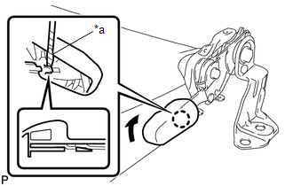
6. REMOVE REAR SEAT LOCK HANDLE
|
(a) Using a screwdriver with its tip wrapped in protective tape, disengage the claw and remove the rear seat lock handle. Text in Illustration
|
|
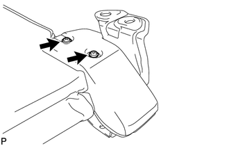
7. REMOVE REAR SEAT CUSHION SUPPORT BRACKET SUB-ASSEMBLY
|
(a) Using T30 "TORX" socket wrench, remove the bolt. |
|
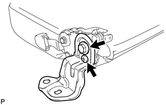
(b) Remove the bolt and rear seat cushion support bracket sub-assembly.
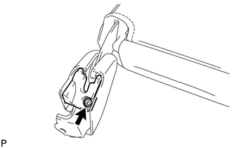
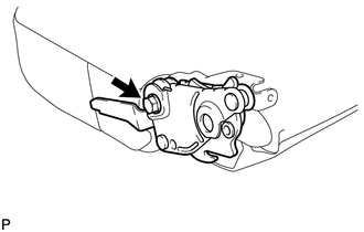
8. REMOVE REAR SEAT LOCK ASSEMBLY
|
(a) Remove the bolt and rear seat lock assembly. |
|
9. REMOVE SEPARATE TYPE REAR SEAT CUSHION COVER
|
(a) Disengage the hook. |
|
(b) Remove the separate type rear seat cushion cover.
10. REMOVE REAR SEAT CUSHION FRAME SUB-ASSEMBLY
|
(a) Remove the rear seat cushion frame sub-assembly from the rear seat cushion pad. |
|
 Components
COMPONENTS
ILLUSTRATION
ILLUSTRATION
...
 Reassembly
REASSEMBLY
CAUTION / NOTICE / HINT
HINT:
The procedure described below is for the LH side. Use the same procedure for
both the LH and RH sides, unless otherwise specified.
PROCEDURE
1. INSTALL ...
Other materials:
Clutch Switch Circuit
DESCRIPTION
While depressing the clutch pedal, the clutch start switch assembly sends a signal
to terminal MTN of the 4 wheel drive control ECU. While the signal is input, switching
between H4 and L4 is possible.
WIRING DIAGRAM
PROCEDURE
1.
READ VALUE USING TECHSTREA ...
Door Control Receiver
Components
COMPONENTS
ILLUSTRATION
Removal
REMOVAL
PROCEDURE
1. REMOVE ROOF HEADLINING ASSEMBLY (for Double Cab)
(See page )
2. REMOVE ROOF HEADLINING ASSEMBLY (for Access Cab)
(See page )
3. REMOVE DOOR CONTROL RECEIVER (w/o Tire Pressure Warning System)
(a) Disconne ...
FCM Destination Information Unmatched (C1AA1)
DESCRIPTION
When the forward recognition camera is replaced with a new one, the new forward
recognition camera attempts to store country specification information received
from the main body ECU (multiplex network body ECU) and ECM. If the country specification
information stored in the forwa ...
