Toyota Tacoma (2015-2018) Service Manual: Disassembly
DISASSEMBLY
PROCEDURE
1. REMOVE KNUCKLE GREASE RETAINER CAP (for 2WD)
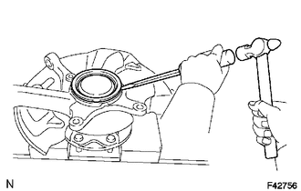
(a) Using a screwdriver and hammer, remove the knuckle grease retainer cap.
2. REMOVE FRONT AXLE HUB OIL SEAL (for 4WD)
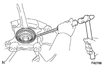
(a) Using a screwdriver and hammer, remove the front axle hub oil seal.
3. REMOVE FRONT WHEEL ADJUSTING NUT (for 2WD)
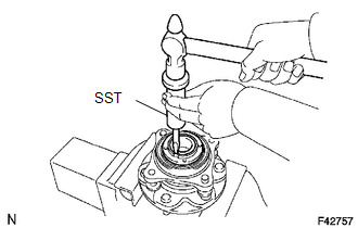
(a) Using SST and a hammer, unstake the front wheel adjusting nut.
SST: 09930-00010
|
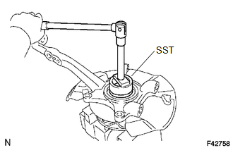
(b) Using SST, remove the front wheel adjusting nut. SST: 09318-12010 |
|
4. REMOVE FRONT AXLE HUB

(a) Remove the 4 bolts and axle hub from the steering knuckle.
(b) Remove the O-ring from the axle hub.
5. REMOVE FRONT AXLE WITH ABS ROTOR BEARING ASSEMBLY
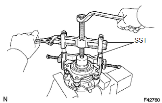
(a) Gently fix the front axle hub in a vise.
(b) Using SST, remove the bearing.
SST: 09710-30021
09710-03051
SST: 09950-40011
09951-04020
09952-04010
09953-04020
09954-04010
09955-04061
09957-04010
09958-04011
6. REMOVE FRONT AXLE HUB OIL SEAL
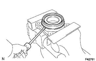
(a) Using a screwdriver, remove the front axle hub oil seal.
 Components
COMPONENTS
ILLUSTRATION
ILLUSTRATION
...
 Reassembly
REASSEMBLY
PROCEDURE
1. INSTALL FRONT AXLE HUB OIL SEAL
(a) Using a brass bar and a hammer, install a new front axle hub oil seal.
NOTICE:
Do not damage the oil seal.
2. INSTALL FRONT AXLE WIT ...
Other materials:
Seat belts
Make sure that all occupants are wearing their seat belts before driving the
vehicle.
■ Correct use of the seat belts
● Extend the shoulder belt so that it comes fully over the shoulder, but does
not come into contact with the neck or slide off the shoulder.
● Position the ...
Satellite Radio Broadcast cannot be Selected or After Selecting Broadcast, Broadcast
cannot be Added into Memory
CAUTION / NOTICE / HINT
NOTICE:
Some satellite radio broadcasts require payment. A contract must be made between
a satellite radio company and the user. If the contract expires, it will not be
possible to listen to the broadcast.
PROCEDURE
1.
CHECK SATELLITE RADIO
...
Stereo Component Amplifier Power Source Circuit
DESCRIPTION
This circuit provides power to the stereo component amplifier assembly.
WIRING DIAGRAM
CAUTION / NOTICE / HINT
Inspect the fuses for circuits related to this system before performing the following
inspection procedure.
PROCEDURE
1.
CHECK HARNESS AND CONNE ...
