Toyota Tacoma (2015-2018) Service Manual: Diagnosis System
DIAGNOSIS SYSTEM
DIAGNOSIS FUNCTION
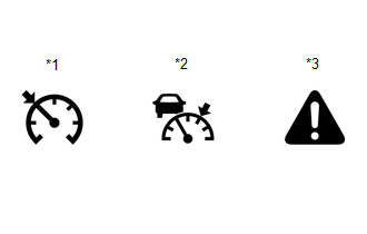
(a) The diagnosis function turns off the cruise control indicator, illuminates the master warning light and displays a warning message when a malfunction is detected. When a malfunction is detected in the dynamic radar cruise control system, DTCs are stored in the ECM or millimeter wave radar sensor assembly.
|
*1 |
Cruise Control Indicator (Constant Speed Control Mode) |
|
*2 |
Cruise Control Indicator (Vehicle-to-vehicle Distance Control Mode) |
|
*3 |
Master Warning Light |
NOTICE:
- If DTCs related to the communication system are stored, "Cruise Control Malfunction Visit Your Dealer", which is displayed in the combination meter assembly, disappears when the system returns to normal.
- If DTCs not related to the communication system are stored, "Cruise Control Malfunction Visit Your Dealer", which is displayed in the combination meter assembly, disappears when the ignition switch off then back ON after the system returns to normal.
DESCRIPTION
(a) The ECM and millimeter wave radar sensor assembly control the dynamic radar cruise control system of the vehicle. The data and DTCs relating to the dynamic radar cruise control system can be read from the DLC3 of the vehicle. Use the Techstream to check and solve the problem.
CHECK DLC3
(a) Check the DLC3.
Click here .gif)
CHECK INDICATOR
(a) Turn the ignition switch to ON.
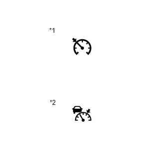
(b) Check that the cruise control indicator illuminates when the dynamic radar cruise control system is turned on using the cruise control main switch (ON-OFF button), and that the indicator turns off when the dynamic radar cruise control system is turned off using the cruise control main switch (ON-OFF button).
|
*1 |
Cruise Control Indicator (Constant Speed Control Mode) |
|
*2 |
Cruise Control Indicator (Vehicle-to-vehicle Distance Control Mode) |
 Road Test
ROAD TEST
PROBLEM SYMPTOM CONFIRMATION
HINT:
The dynamic radar cruise control system has 2 cruise control modes:
constant speed control mode and vehicle-to-vehicle distance control mode ...
 Problem Symptoms Table
PROBLEM SYMPTOMS TABLE
NOTICE:
Before replacing the ECM, refer to Registration.
w/o Smart Key System: Click here
w/ Smart Key System: Click here
When the millimeter wave rad ...
Other materials:
Pcv Valve
Components
COMPONENTS
ILLUSTRATION
Inspection
INSPECTION
PROCEDURE
1. INSPECT PCV VALVE SUB-ASSEMBLY
(a) Install a clean hose to the PCV valve sub-assembly.
(b) Check the PCV valve sub-assembly operation.
(1) Blow air into the cylinder head cover sub-assembly LH side and check that
...
Installation
INSTALLATION
PROCEDURE
1. SET NO. 1 CYLINDER TO TDC/COMPRESSION
2. INSTALL CAMSHAFT TIMING GEAR BOLT
NOTICE:
There are different types of camshaft timing gearbolts. Make sure to check the
identification mark todetermine the tightening torque.
*a
Identification Mark ...
Installation
INSTALLATION
CAUTION / NOTICE / HINT
HINT:
Perform "Inspection After Repairs" after replacing the fuel injector assembly
(See page ).
PROCEDURE
1. INSTALL FUEL INJECTOR SEAL
(a) Apply engine conditioner to the fuel injector assembly area shown
in the illustration. U ...
