Toyota Tacoma (2015-2018) Service Manual: Cruise Control Main Switch
Components
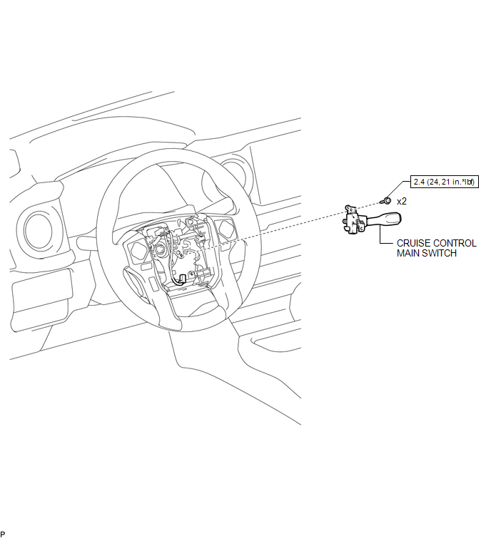
COMPONENTS
ILLUSTRATION
Removal
REMOVAL
PROCEDURE
1. REMOVE STEERING PAD ASSEMBLY
(See page .gif) )
)
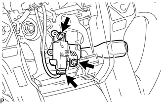
2. REMOVE CRUISE CONTROL MAIN SWITCH
|
(a) Disconnect the connector and remove the 2 screws. |
|
|
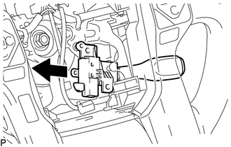
(b) Remove the cruise control main switch from the steering wheel. |
|
Installation
INSTALLATION
PROCEDURE
1. INSTALL CRUISE CONTROL MAIN SWITCH
|
(a) Install the cruise control main switch with the 2 screws and connect the connector. Torque: 2.4 N·m {24 kgf·cm, 21 in·lbf} |
|
.png)
2. INSTALL STEERING PAD ASSEMBLY
(See page .gif) )
)
 Clutch Switch
Components
COMPONENTS
ILLUSTRATION
Removal
REMOVAL
PROCEDURE
1. PRECAUTION
NOTICE:
After turning the engine switch off, waiting time may be required before disconnecting
the cable from ...

Other materials:
Reassembly
REASSEMBLY
PROCEDURE
1. INSTALL GENERATOR DRIVE END FRAME BEARING
(a) Using SST and a press, press in a new generator drive end frame bearing.
SST: 09950-60010
09951-00470
SST: 09950-70010
09951-07100
(b) Fit the ta ...
Adjustment
ADJUSTMENT
PROCEDURE
1. PREPARE VEHICLE FOR FOG LIGHT AIMING ADJUSTMENT
(a) Prepare the vehicle:
HINT:
Ensure that there is no damage or deformation to the body around the
fog lights.
Fill the fuel tank.
Make sure that the oil is filled to the specified level.
Make sure ...
ECU Power Source Circuit
WIRING DIAGRAM
CAUTION / NOTICE / HINT
NOTICE:
Inspect the fuses for circuits related to this system before performing the following
inspection procedure.
PROCEDURE
1.
INSPECT BATTERY
(a) Check the battery voltage.
Standard voltage:
11 to 14 V
NG
...
