Toyota Tacoma (2015-2018) Service Manual: Components
COMPONENTS
ILLUSTRATION
ILLUSTRATION
ILLUSTRATION
|
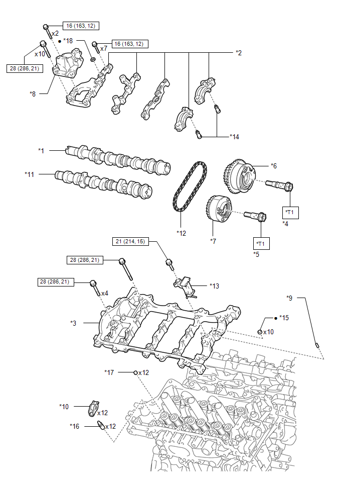
*1 |
CAMSHAFT |
*2 |
CAMSHAFT BEARING CAP |
|
*3 |
CAMSHAFT HOUSING SUB-ASSEMBLY RH |
*4 |
CAMSHAFT TIMING GEAR BOLT (for Intake Side of Bank 1) |
|
*5 |
CAMSHAFT TIMING GEAR BOLT (for Exhaust Side of Bank 1) |
*6 |
CAMSHAFT TIMING GEAR ASSEMBLY |
|
*7 |
CAMSHAFT TIMING EXHAUST GEAR ASSEMBLY RH |
*8 |
FUEL PUMP LIFTER HOUSING |
|
*9 |
NO. 1 STRAIGHT PIN |
*10 |
NO. 1 VALVE ROCKER ARM SUB-ASSEMBLY |
|
*11 |
NO. 2 CAMSHAFT |
*12 |
NO. 2 CHAIN SUB-ASSEMBLY |
|
*13 |
NO. 2 CHAIN TENSIONER ASSEMBLY |
*14 |
OIL CONTROL VALVE FILTER RH |
|
*15 |
RING PIN |
*16 |
VALVE LASH ADJUSTER ASSEMBLY |
|
*17 |
VALVE STEM CAP |
*18 |
GASKET |
.png) |
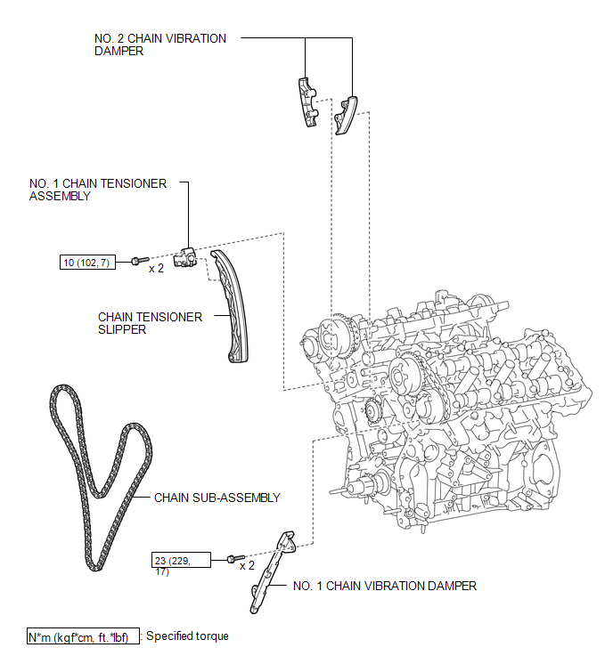
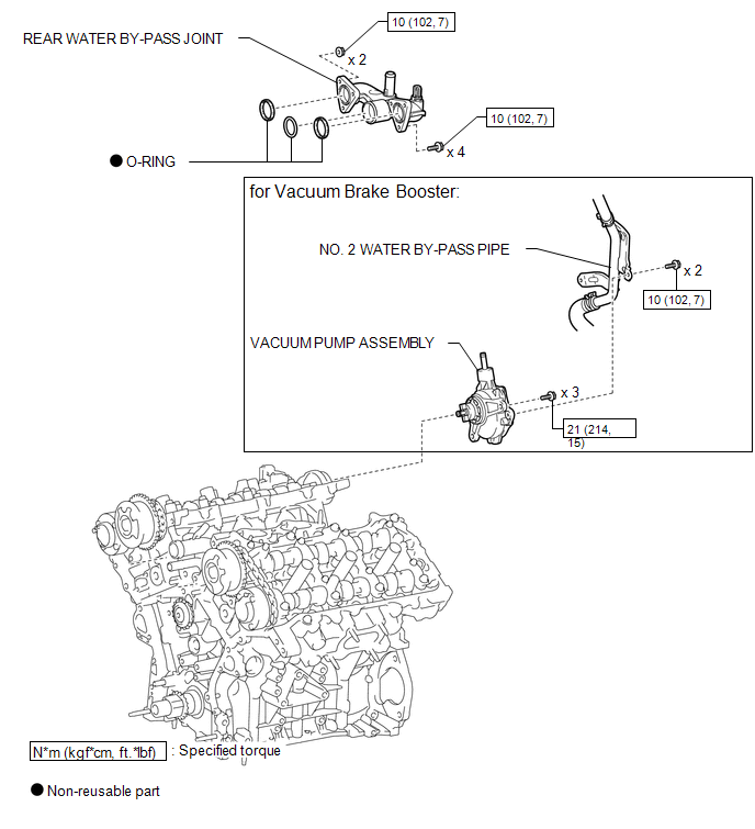
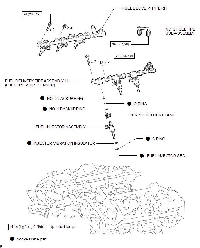
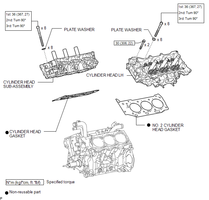
N*m (kgf*cm, ft.*lbf): Specified torque |
â—Ź |
Non-reusable part |
|
*T1 |
Type A: 120 N*m (1224 kgf*cm, 89 ft.*lbf) Type B: 95 N*m (969 kgf*cm, 70 ft.*lbf) |
- |
- |
ILLUSTRATION
|
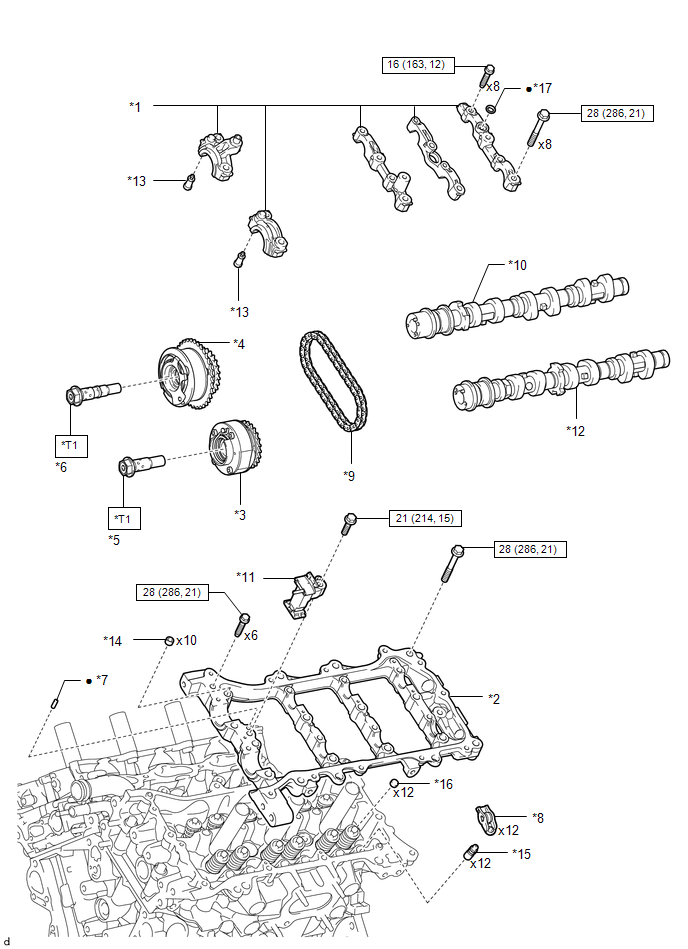
*1 |
CAMSHAFT BEARING CAP |
*2 |
CAMSHAFT HOUSING SUB-ASSEMBLY LH |
|
*3 |
CAMSHAFT TIMING EXHAUST GEAR ASSEMBLY LH |
*4 |
CAMSHAFT TIMING GEAR ASSEMBLY |
|
*5 |
CAMSHAFT TIMING GEAR BOLT (for Exhaust Side of Bank 2) |
*6 |
CAMSHAFT TIMING GEAR BOLT (for Intake Side of Bank 2) |
|
*7 |
NO. 1 STRAIGHT PIN |
*8 |
NO. 1 VALVE ROCKER ARM SUB-ASSEMBLY |
|
*9 |
NO. 2 CHAIN SUB-ASSEMBLY |
*10 |
NO. 3 CAMSHAFT SUB-ASSEMBLY |
|
*11 |
NO. 3 CHAIN TENSIONER ASSEMBLY |
*12 |
NO. 4 CAMSHAFT SUB-ASSEMBLY |
|
*13 |
OIL CONTROL VALVE FILTER LH |
*14 |
RING PIN |
|
*15 |
VALVE LASH ADJUSTER ASSEMBLY |
*16 |
VALVE STEM CAP |
|
*17 |
GASKET |
- |
- |
|
|
N*m (kgf*cm, ft.*lbf): Specified torque |
â—Ź |
Non-reusable part |
|
*T1 |
Type A: 120 N*m (1224 kgf*cm, 89 ft.*lbf) Type B: 95 N*m (969 kgf*cm, 70 ft.*lbf) |
- |
- |
ILLUSTRATION
ILLUSTRATION

 Removal
REMOVAL
PROCEDURE
1. REMOVE TIMING CHAIN COVER ASSEMBLY
(See page )
2. SEPARATE NO. 2 WATER BY-PASS PIPE (for Vacuum Brake Booster)
3. REMOVE VACUUM PUMP ASSEMBLY (for Vacuum Brake Booster)
...
Other materials:
Dtc Check / Clear
DTC CHECK / CLEAR
1. CHECK FOR DTC
HINT:
When using the Techstream with the engine switch off to troubleshoot:
Connect the Techstream to the DLC3 and turn a courtesy light switch on and off
at 1.5-second intervals until communication between the Techstream and vehicle begins.
(a) Connect the ...
Parts Location
PARTS LOCATION
ILLUSTRATION
ILLUSTRATION
ILLUSTRATION
ILLUSTRATION
...
Terminals Of Ecu
TERMINALS OF ECU
1. CHECK MAIN BODY ECU (MULTIPLEX NETWORK BODY ECU)
Text in Illustration
*1
Main Body ECU (Multiplex Network Body ECU)
-
-
(a) Disconnect the driver side junction block and main body ECU (multiplex network
body ECU) connect ...
