Toyota Tacoma (2015-2018) Service Manual: Components
COMPONENTS
ILLUSTRATION
ILLUSTRATION
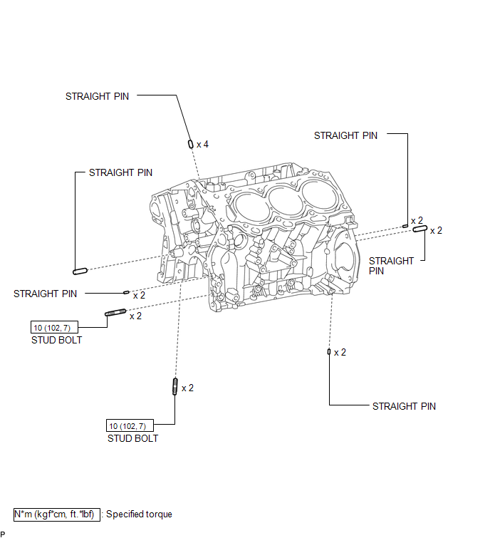
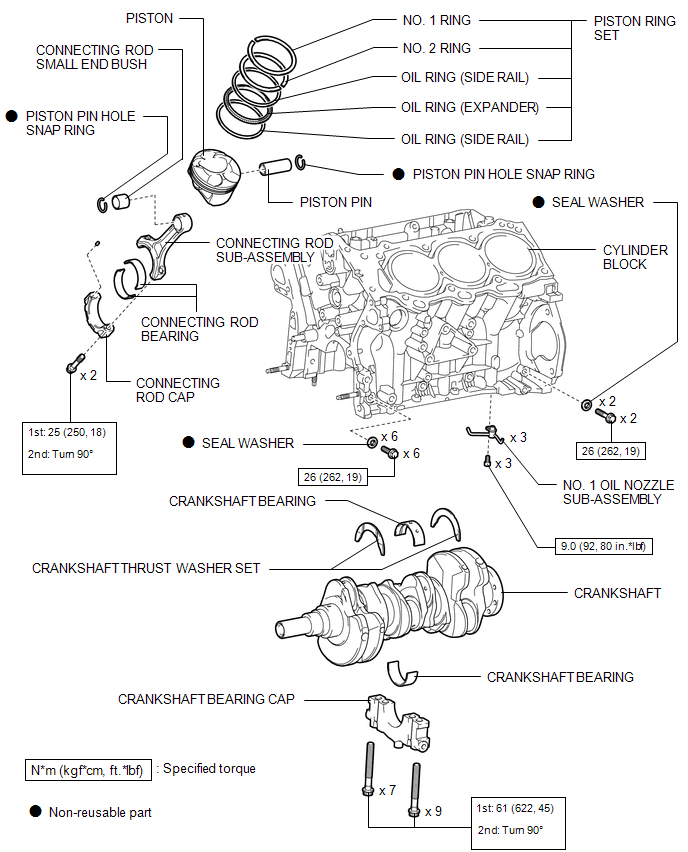
 Cylinder Block
...
 Precaution
PRECAUTION
HINT:
Any digits beyond the 0.01 mm (1/1000 in.) place for standard, minimum
and maximum values should be used as a reference only.
When both standard and maximum or minim ...
Other materials:
Terminals Of Ecu
TERMINALS OF ECU
1. NAVIGATION RECEIVER ASSEMBLY
Terminal No. (Symbols)
Wiring Color
Terminal Description
Condition
Specified Condition
N19-3 (ACC2) - N24-7 (GND1)*3
Y - W-B
Power source (ACC)
...
Front Axle Hub Bolt
Installation
INSTALLATION
PROCEDURE
1. INSTALL FRONT AXLE HUB BOLT
(a) Install a new hub bolt through the axle hub.
(b) Install the washer plate, as shown in the illustration, through the hub bolt,
and install the hub bolt by tightening the hub nut.
2. INSTALL FRONT DISC
3. INSTALL FRON ...
Manual Transmission Unit
Components
COMPONENTS
ILLUSTRATION
ILLUSTRATION
*1
SHIFT DETENT BALL PLUG
*2
SHIFT DETENT BALL COMPRESSION SPRING
*3
MANUAL TRANSMISSION FILLER PLUG
*4
SHAFT DETENT BALL
*5
...
