Toyota Tacoma (2015-2018) Service Manual: Components
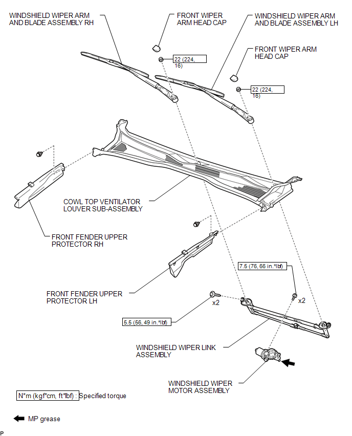
COMPONENTS
ILLUSTRATION

 On-vehicle Inspection
ON-VEHICLE INSPECTION
PROCEDURE
1. INSPECT FRONT WIPER MOTOR (for Driver Side)
Text in Illustration
*a
Matchmark
(a) Check the stop (park) position.
(b) Operate t ...
Other materials:
Parts Location
PARTS LOCATION
ILLUSTRATION
*A
for Automatic Transmission
*B
for Manual Transmission
*C
for 4WD
-
-
*1
FRONT SPEED SENSOR LH
*2
FRONT SPEED SENSOR RH
...
Removal
REMOVAL
PROCEDURE
1. REMOVE REAR SEAT CUSHION ASSEMBLY
(a) Remove the 2 bolts and rear seat cushion assembly.
2. REMOVE REAR SEATBACK HINGE COVER
(a) for LH Side:
(1) Disengage the 6 claws to remove the 2 rear seatback hinge cov ...
Reservoir Level Switch Disconnected (C1453,C1454)
DESCRIPTION
The brake fluid level warning switch sends the appropriate signal to the skid
control ECU (master cylinder solenoid) when the brake fluid level drops.
DTC Code
DTC Detection Condition
Trouble Area
C1453
With the ECU termina ...
