Toyota Tacoma (2015-2018) Service Manual: Short in Front Passenger Side Knee Airbag Squib Circuit (B1865/65-B1868/65)
DESCRIPTION
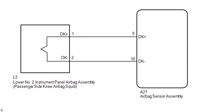
The passenger side knee airbag squib circuit consists of the airbag sensor assembly and lower No. 2 instrument panel airbag assembly.
The airbag sensor assembly uses this circuit to deploy the airbag when deployment conditions are met. These DTCs are stored when a malfunction is detected in the passenger side knee airbag squib circuit.
|
DTC No. |
DTC Detection Condition |
Trouble Area |
|---|---|---|
|
B1865/65 |
|
|
|
B1866/65 |
|
|
|
B1867/65 |
|
|
|
B1868/65 |
|
WIRING DIAGRAM
CAUTION / NOTICE / HINT
NOTICE:
After turning the ignition switch off, waiting time may be required before disconnecting
the cable from the negative (-) battery terminal. Therefore, make sure to read the
disconnecting the cable from the negative (-) battery terminal notices before proceeding
with work (See page .gif) ).
).
HINT:
- Perform the simulation method by selecting check mode (Signal Check)
using the Techstream (See page ).
- After selecting check mode (Signal Check), perform the simulation method
by wiggling each connector of the airbag system or driving the vehicle on
a city road or rough road (See page
).
PROCEDURE
|
1. |
CHECK CONNECTORS |
|
(a) Turn the ignition switch off. |
|
.png)
(b) Disconnect the cable from the negative (-) battery terminal.
CAUTION:
Wait at least 90 seconds after disconnecting the cable from the negative (-) battery terminal to disable the SRS system.
(c) Check that the connectors are properly connected to the lower No. 2 instrument panel airbag assembly and airbag sensor assembly.
OK:
The connectors are properly connected.
HINT:
If the connectors are not connected securely, reconnect the connectors and proceed to the next inspection.
(d) Disconnect the connectors from the lower No. 2 instrument panel airbag assembly and airbag sensor assembly.
(e) Check that the terminals of the connectors are not damaged.
OK:
The terminals are not deformed or damaged.
(f) Check that the instrument panel wire connector (on the lower No. 2 instrument panel airbag assembly side) is not damaged.
OK:
The lock button is not disengaged, and the claw of the lock is not deformed or damaged.
(g) Check that the short spring for the instrument panel wire with the activation prevention mechanism are not deformed or damaged.
OK:
The short spring is not deformed or damaged.
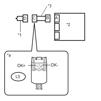
Text in Illustration|
*1 |
Passenger Side Knee Airbag Squib |
|
*2 |
Airbag Sensor Assembly |
|
*3 |
Instrument Panel Wire |
| NG | .gif) |
REPLACE INSTRUMENT PANEL WIRE |
|
.gif)
|
2. |
CHECK LOWER NO. 2 INSTRUMENT PANEL AIRBAG ASSEMBLY (PASSENGER SIDE KNEE AIRBAG SQUIB) |
|
(a) Connect the connector to the airbag sensor assembly. |
|
.png)
(b) Connect SST (resistance 2.1 Ω) to connector C.
CAUTION:
Never connect the tester to the lower No. 2 instrument panel airbag assembly (passenger side knee airbag squib) for measurement, as this may lead to a serious injury due to airbag deployment.
NOTICE:
- Do not forcibly insert SST into the terminals of the connector when connecting it.
- Insert SST straight into the terminals of the connector.
SST: 09843-18061
(c) Connect the cable to the negative (-) battery terminal.
(d) Clear the DTCs stored in memory (See page
).
(e) Turn the ignition switch off.
(f) Turn the ignition switch to ON, and wait for at least 60 seconds.
(g) Check for DTCs (See page ).
OK:
DTC B1860/64, B1861/64, B1862/64 or B1863/64 is not output.
HINT:
Codes other than DTCs B1860/64, B1861/64, B1862/64 and B1863/64 may be output at this time, but they are not related to this check.
(h) Turn the ignition switch off.
(i) Disconnect the cable from the negative (-) battery terminal.
CAUTION:
Wait at least 90 seconds after disconnecting the cable from the negative (-) battery terminal to disable the SRS system.
(j) Disconnect SST from connector C.
Text in Illustration|
*1 |
Passenger Side Knee Airbag Squib |
|
*2 |
Airbag Sensor Assembly |
|
*a |
Front view of wire harness connector (to Lower No. 2 Instrument Panel Airbag Assembly) |
| OK | |
REPLACE LOWER NO. 2 INSTRUMENT PANEL AIRBAG ASSEMBLY |
|
|
3. |
CHECK INSTRUMENT PANEL WIRE |
|
(a) Disconnect the instrument panel wire from the airbag sensor assembly. |
|
(b) Check for a short to B+ in the circuit.
(1) Connect the cable to the negative (-) battery terminal.
(2) Turn the ignition switch to ON.
(3) Measure the voltage according to the value(s) in the table below.
Standard Voltage:
|
Tester Connection |
Switch Condition |
Specified Condition |
|---|---|---|
|
L5-1 (DK+) - Body ground |
Ignition switch ON |
Below 1 V |
|
L5-2 (DK-) - Body ground |
Ignition switch ON |
Below 1 V |
(4) Turn the ignition switch off.
(5) Disconnect the cable from the negative (-) battery terminal.
CAUTION:
Wait at least 90 seconds after disconnecting the cable from the negative (-) battery terminal to disable the SRS system.
(c) Check for an open in the circuit.
(1) Measure the resistance according to the value(s) in the table below.
Standard Resistance:
|
Tester Connection |
Condition |
Specified Condition |
|---|---|---|
|
L5-1 (DK+) - L5-2 (DK-) |
Always |
Below 1 Ω |
(d) Check for a short to ground in the circuit.
(1) Measure the resistance according to the value(s) in the table below.
Standard Resistance:
|
Tester Connection |
Condition |
Specified Condition |
|---|---|---|
|
L5-1 (DK+) - Body ground |
Always |
1 MΩ or higher |
|
L5-2 (DK-) - Body ground |
Always |
1 MΩ or higher |
(e) Check for a short in the circuit.
(1) Release the activation prevention mechanism built into connector B (See page
).
(2) Measure the resistance according to the value(s) in the table below.
Standard Resistance:
|
Tester Connection |
Condition |
Specified Condition |
|---|---|---|
|
L5-1 (DK+) - L5-2 (DK-) |
Always |
1 MΩ or higher |
(3) Restore the released activation prevention mechanism of connector B to the original condition.
Text in Illustration|
*1 |
Passenger Side Knee Airbag Squib |
|
*2 |
Airbag Sensor Assembly |
|
*3 |
Instrument Panel Wire |
|
*a |
Front view of wire harness connector (to Lower No. 2 Instrument Panel Airbag Assembly) |
| NG | |
REPLACE INSTRUMENT PANEL WIRE |
|
|
4. |
CHECK DTC |
|
(a) Connect the connectors to the lower No. 2 instrument panel airbag assembly and airbag sensor assembly. |
|
.png)
(b) Connect the cable to the negative (-) battery terminal.
(c) Turn the ignition switch to ON, and wait for at least 60 seconds.
(d) Clear the DTCs stored in memory (See page
).
(e) Turn the ignition switch off.
(f) Turn the ignition switch to ON, and wait for at least 60 seconds.
(g) Check for DTCs (See page ).
OK:
DTC B1860/64, B1861/64, B1862/64 or B1863/64 is not output.
HINT:
Codes other than DTCs B1860/64, B1861/64, B1862/64 and B1863/64 may be output at this time, but they are not related to this check.
Text in Illustration|
*1 |
Passenger Side Knee Airbag Squib |
|
*2 |
Airbag Sensor Assembly |
| OK | |
USE SIMULATION METHOD TO CHECK |
| NG | |
REPLACE AIRBAG SENSOR ASSEMBLY |
 Short in Driver Side Knee Airbag Squib Circuit (B1860/64-B1863/64)
DESCRIPTION
The driver side knee airbag squib circuit consists of the airbag sensor assembly
and lower No. 1 instrument panel airbag assembly.
The airbag sensor assembly uses this circuit to deplo ...
 Short in Front Passenger Side Squib Circuit (B1805/52-B1808/52)
DESCRIPTION
The front passenger side squib circuit consists of the airbag sensor assembly
and the instrument panel passenger without door airbag assembly.
The circuit instructs the SRS to deploy w ...
Other materials:
Steering Angle Sensor (C1A47)
DESCRIPTION
The forward recognition camera receives steering angle information from the spiral
cable with sensor sub-assembly. If the forward recognition camera detects a spiral
cable with sensor sub-assembly malfunction, DTC C1A47 is stored.
DTC No.
Detection Item
...
Customize Parameters
CUSTOMIZE PARAMETERS
PROCEDURE
1. CUSTOMIZE SLIDING ROOF SYSTEM
HINT:
The following items can be customized.
NOTICE:
When the customer requests a change in a function, first make sure that
the function(s) can be customized.
Be sure to make notes of the current settings before c ...
Sliding Roof does not Move by Operating Sliding Roof Control Switch
DESCRIPTION
The sliding roof ECU (sliding roof drive gear sub-assembly) receives slide and
tilt signals when the sliding roof switch is operated and drives its built-in motor.
WIRING DIAGRAM
CAUTION / NOTICE / HINT
NOTICE:
Inspect the fuses for circuits related to this system before ...
