Toyota Tacoma (2015-2018) Service Manual: Components
COMPONENTS
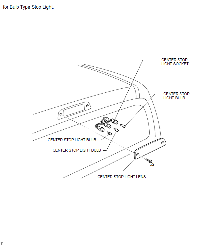
ILLUSTRATION
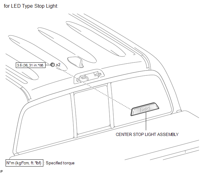
ILLUSTRATION

 Inspection
INSPECTION
PROCEDURE
1. INSPECT CENTER STOP LIGHT ASSEMBLY (for LED Type Stop Light)
(a) Check the illuminates.
(1) Apply battery voltage to the connector and check the light illuminati ...
Other materials:
IG Supply Voltage Low (C120B)
DESCRIPTION
DTC No.
Detection Item
DTC Detection Condition
Trouble Area
C120B
IG Supply Voltage Low
Master cylinder pressure sensor power supply voltage decrease occurs
or history of voltage decrease exists, and ...
Installation
INSTALLATION
PROCEDURE
1. INSTALL ENGINE WATER PUMP ASSEMBLY
(a) Install the engine water pump assembly and a new gasket to the timing
chain cover assembly with the 15 bolts.
Torque:
for Bolt A and B :
11 N·m {112 kgf·cm, 8 ft·lbf}
for Bolt C :
21 N·m {214 kgf ...
Diagnosis System
DIAGNOSIS SYSTEM
1. DESCRIPTION
The 4 wheel drive control ECU records DTCs when the ECU detects a malfunction
in the ECU itself or in system circuits.
The DTCs can be read through the DLC3 of the vehicle. When the system seems to
be malfunctioning, use the Techstream to check for malfunctions ...
