Toyota Tacoma (2015-2018) Service Manual: Components
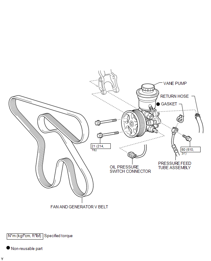
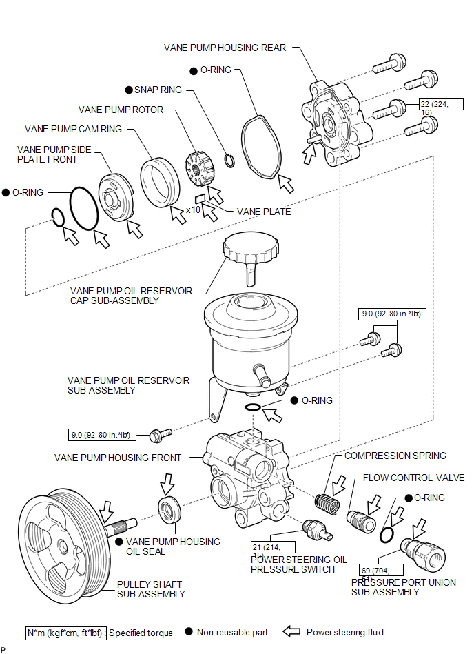
COMPONENTS
ILLUSTRATION
ILLUSTRATION

 Disassembly
DISASSEMBLY
PROCEDURE
1. FIX VANE PUMP
(a) Using SST, fix the vane pump assembly in a vise.
SST: 09630-00014
09631-00132
NOTICE:
When using a vise, do not overtighten it.
2. REMOVE VANE PUMP ...
Other materials:
Fog Light Relay
Inspection
INSPECTION
PROCEDURE
1. INSPECT FOG LIGHT RELAY
(a) Check the resistance.
(1) Using an ohmmeter, measure the resistance between the terminals.
Standard:
Tester Connection
Specified Condition
3-5
10 kΩ or higher
...
On-vehicle Inspection
ON-VEHICLE INSPECTION
PROCEDURE
1. INSPECT CAMSHAFT TIMING GEAR BOLT
(a) Remove the camshaft timing oil control solenoid assembly (See page
).
(b) Check that the plunger strokes when the plunger in the center of
the camshaft timing gear bolt is pressed.
Standard stroke:
4 ...
Terminals Of Ecu
TERMINALS OF ECU
1. CHECK MAIN BODY ECU (MULTIPLEX NETWORK BODY ECU) AND DRIVER SIDE JUNCTION
BLOCK
(a) Disconnect the main body ECU (multiplex network body ECU) connectors.
Text in Illustration
*1
Main Body ECU (Multiplex Network Body ECU)
-
-
...
