Toyota Tacoma (2015-2018) Service Manual: Components
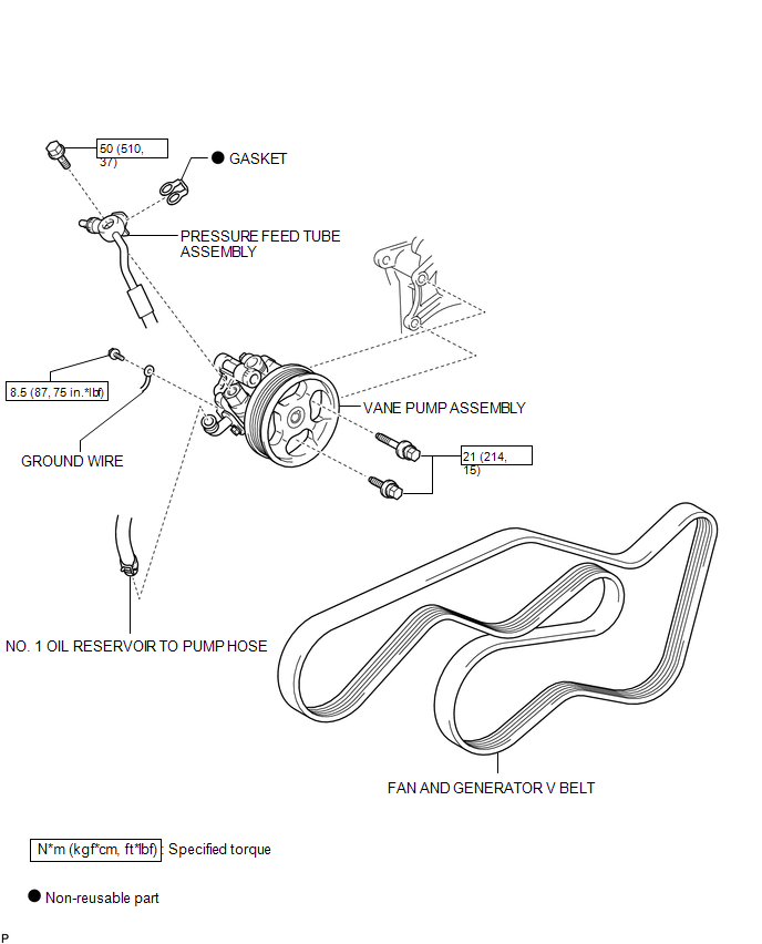
COMPONENTS
ILLUSTRATION
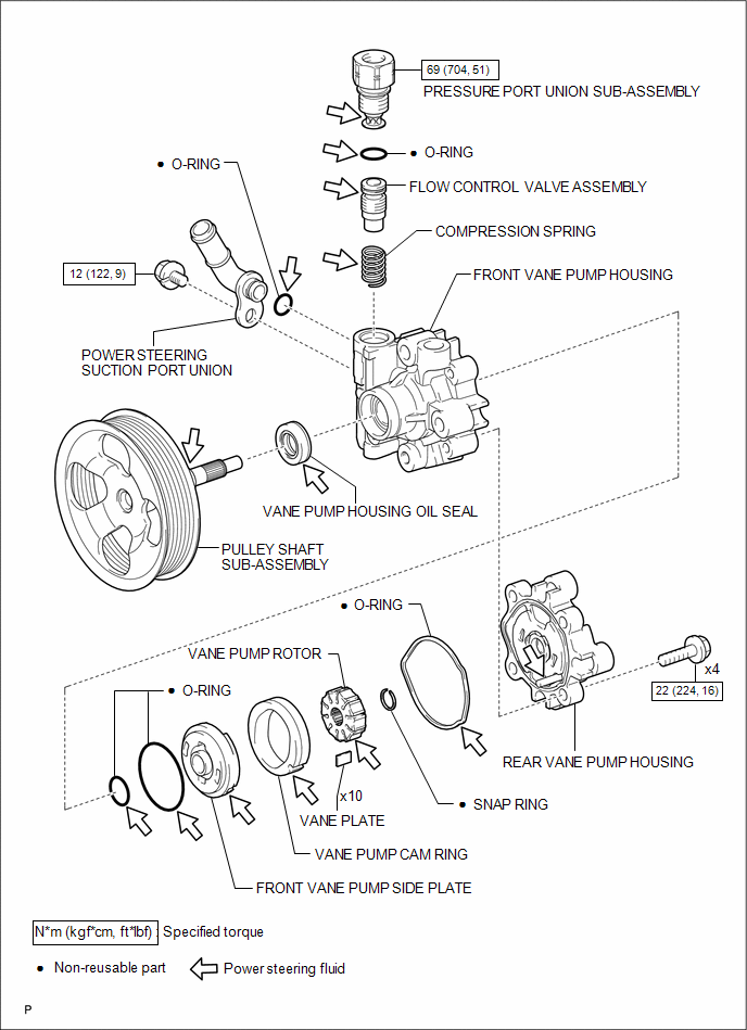
ILLUSTRATION

 Disassembly
DISASSEMBLY
PROCEDURE
1. FIX VANE PUMP ASSEMBLY
(a) Using SST, fix the vane pump assembly in a vise.
SST: 09630-00014
09631-00132
NOTICE:
When using a vise, do not overtighte ...
Other materials:
Rear Speed Sensor
Removal
REMOVAL
PROCEDURE
1. PRECAUTION
NOTICE:
After turning the ignition switch off, waiting time may be required before disconnecting
the cable from the negative (-) battery terminal.
Therefore, make sure to read the disconnecting the cable from the negative (-)
battery terminal notic ...
Removal
REMOVAL
CAUTION / NOTICE / HINT
NOTICE:
Before starting the work, make sure that the ignition switch is off
and depress the brake pedal more than 20 times.
As high pressure is applied to the No. 1 brake actuator tube, never
deform it.
Do not turn the ignition switch to ON ...
Problem Symptoms Table
PROBLEM SYMPTOMS TABLE
HINT:
Use the table below to help determine the cause of problem symptoms.
If multiple suspected areas are listed, the potential causes of the symptoms
are listed in order of probability in the "Suspected Area" column of the
table. Check each sy ...
