Toyota Tacoma (2005–2015) Owners Manual: Compass (vehicles with auto anti-glare inside rear view mirror)
The compass on the inside rear view mirror indicates the direction in which the vehicle is heading.
■ Operation
 Type A
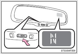
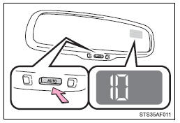
To turn the compass on or off, press the button.
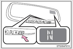
 Type B
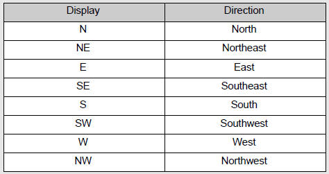
■ Displays and directions
Calibrating the compass
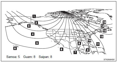
The direction display deviates from the true direction determined by the earth’s magnetic field. The amount of deviation varies depending on the geographic position of the vehicle.
If you cross over one of the map boundaries shown in the illustration, the compass will deviate.
To obtain higher precision or perfect calibration, refer to “Deviation calibration”.
■ Deviation calibration
 Stop the vehicle where it is safe
to drive in a circle.
Stop the vehicle where it is safe
to drive in a circle.
 Press the button until a number
(1 to 15) appears on the compass display.
Press the button until a number
(1 to 15) appears on the compass display.
 Type A
Type B
 Press the button, and referring
to the map above, select the number of the zone where you are.
Press the button, and referring
to the map above, select the number of the zone where you are.
If the direction is displayed several seconds after adjustment, the calibration is complete.
■ Circling calibration
When “C” appears on the display, drive the vehicle at 5 mph (8 km/h) or less in a circle until a direction is displayed.
If there is not enough space to drive in a circle, drive around the block until the direction is displayed.
■Conditions unfavorable to correct operation
The compass may not show the correct direction in the following conditions: ●The vehicle is stopped immediately after turning.
●The vehicle is on an inclined surface.
●The vehicle is in a place where the earth‚Äôs magnetic field is subject to interference by artificial magnetic fields (underground car park/parking lot, under a steel tower, between buildings, roof car park/parking lot, near an intersection, near a large vehicle, etc.).
●The vehicle has become magnetized.
(There is a magnet or metal object near the inside rear view mirror.) ●The battery has been disconnected.
●A door is open.
CAUTION
■While driving the vehicle
Do not adjust the display. Adjust the display only when the vehicle is stopped.
■When doing the circling calibration
Secure a wide space, and watch out for people and vehicles in the vicinity.
Do not violate any local traffic rules while performing circling calibration.
NOTICE
■To avoid the compass malfunctions
Do not place magnets or any metal objects near the inside rear view mirror.
Doing this may cause the compass sensor to malfunction.
■When doing the circling calibration
●Do not perform a circling calibration of the compass in a place where the earth‚Äôs magnetic field is subject to interference by artificial magnetic fields.
●During calibration, do not operate electric systems (power windows, etc.) as they may interfere with the calibration.
 Garage door opener
The garage door opener can be trained to operate garage doors, gates, entry
doors, door locks, home lighting systems, security systems, and other devices.
The garage door opener (HomeLink® Univers ...

Other materials:
Problem Symptoms Table
PROBLEM SYMPTOMS TABLE
HINT:
Use the table below to help determine the cause of problem symptoms.
If multiple suspected areas are listed, the potential causes of the symptoms
are listed in order of probability in the "Suspected Area" column of the
table. Check each sy ...
Problem Symptoms Table
PROBLEM SYMPTOMS TABLE
HINT:
Use the table below to help determine the cause of problem symptoms. If multiple
suspected areas are listed, the potential causes of the symptoms are listed in order
of probability in the "Suspected Area" column of the table. Check each symptom by
check ...
Terminals Of Ecu
TERMINALS OF ECU
1. CHECK 4 WHEEL DRIVE CONTROL ECU
Text in Illustration
*a
Component with harness connected
(4 Wheel Drive Control ECU)
-
-
(a) Measure the resistance and voltage according to the value(s) in the table
below.
...
