Toyota Tacoma (2015-2018) Service Manual: Clutch Accumulator
Components
COMPONENTS
ILLUSTRATION
Installation
INSTALLATION
PROCEDURE
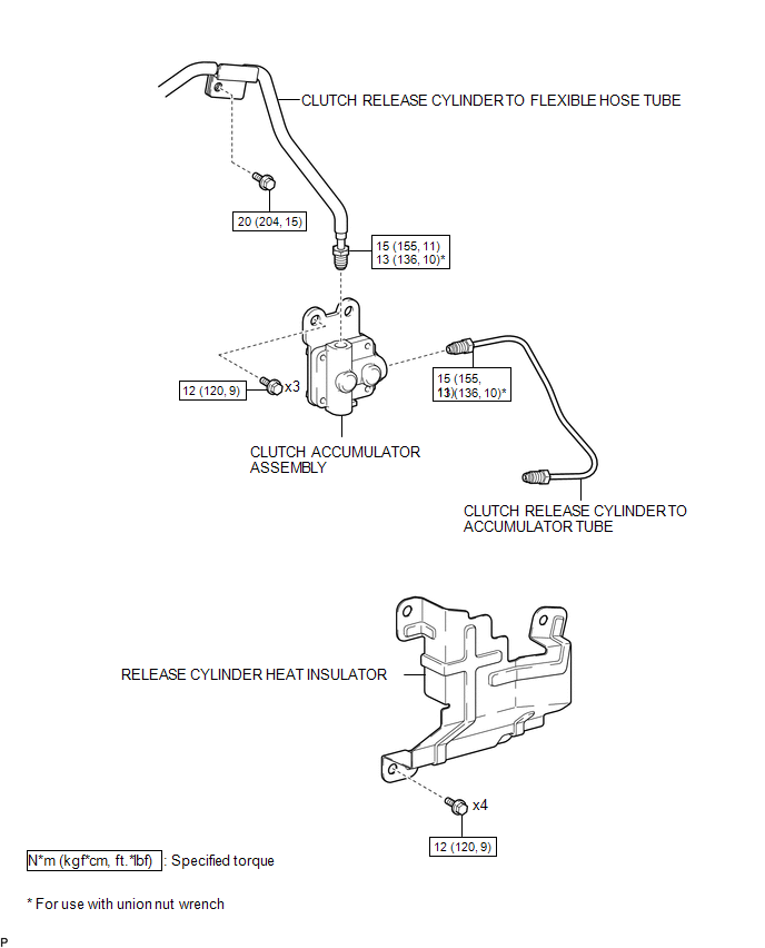
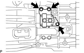
1. INSTALL CLUTCH ACCUMULATOR ASSEMBLY
(a) Install the clutch accumulator assembly to the manual transmission assembly with the 3 bolts.
Torque:
12 N·m {120 kgf·cm, 9 ft·lbf}
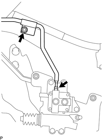
(b) Using a union nut wrench, connect the clutch release cylinder to flexible hose tube to the clutch accumulator assembly.
Torque:
Specified tightening torque :
15 N·m {155 kgf·cm, 11 ft·lbf}
HINT:
- Calculate the torque wrench reading when changing the fulcrum length
of the torque wrench (See page
.gif) ).
). - When using a union nut wrench (fulcrum length of 22 mm (0.866 in.)) + torque wrench (fulcrum length of 162 mm (6.38 in.)): 13 N*m (136 kgf*cm, 10 ft.*lbf)
(c) Install the clutch release cylinder to flexible hose tube to the manual transmission assembly with the bolt.
Torque:
20 N·m {204 kgf·cm, 15 ft·lbf}
2. INSTALL CLUTCH RELEASE CYLINDER TO ACCUMULATOR TUBE
3. INSTALL RELEASE CYLINDER HEAT INSULATOR
4. INSTALL FRONT PROPELLER SHAFT ASSEMBLY
(See page )
5. FILL RESERVOIR WITH BRAKE FLUID
6. BLEED CLUTCH LINE
7. CHECK FLUID LEVEL IN RESERVOIR
8. INSPECT FOR CLUTCH FLUID LEAK
Removal
REMOVAL
PROCEDURE
1. DRAIN CLUTCH FLUID
2. REMOVE FRONT PROPELLER SHAFT ASSEMBLY
(See page .gif) )
)
3. REMOVE RELEASE CYLINDER HEAT INSULATOR
4. REMOVE CLUTCH RELEASE CYLINDER TO ACCUMULATOR TUBE
5. REMOVE CLUTCH ACCUMULATOR ASSEMBLY
|
(a) Using a union nut wrench, disconnect the clutch release cylinder to flexible hose tube from the clutch accumulator assembly. HINT: Use a container to catch the fluid. |
|
(b) Remove the bolt and separate the clutch release cylinder to flexible hose tube from the manual transmission assembly.
|
(c) Remove the 3 bolts and clutch accumulator assembly from the manual transmission assembly. |
|
 Clutch
...
 Clutch Master Cylinder
Components
COMPONENTS
ILLUSTRATION
Installation
INSTALLATION
PROCEDURE
1. INSTALL CLUTCH MASTER CYLINDER ASSEMBLY
(a) Install the clutch master cylinder assembly to the clutch pedal suppo ...
Other materials:
Multi-terrain Select Indicator Light Remains ON
DESCRIPTION
Refer to Multi-terrain Select Indicator Light does not Come ON (See page
).
WIRING DIAGRAM
CAUTION / NOTICE / HINT
NOTICE:
When replacing the skid control ECU (master cylinder solenoid), perform
calibration (See page
).
Inspect the fuses for circuits related ...
Light bulbs
You may replace the following bulbs yourself. The difficulty level of replacement
varies depending on the bulb. If necessary bulb replacement seems difficult to perform,
contact your Toyota dealer.
For more information about replacing other light bulbs, contact your Toyota dealer.
■ Prep ...
Diagnosis System
DIAGNOSIS SYSTEM
CHECK DLC3
(a) Check the DLC3.
Click here
FUNCTION OF WARNING INDICATOR AND MESSAGE
(a) If the lane departure alert system is not functioning properly, the driver
is warned by the lane departure alert indicator and multi-information display warning
message on the combinat ...
