Toyota Tacoma (2015-2018) Service Manual: Center Differential Lock Position Switch (C1282)
DESCRIPTION
DTC C1282 is stored only in test mode.
|
DTC Code |
DTC Detection Condition |
Trouble Area |
|---|---|---|
|
C1282 |
Stored during test mode. |
|
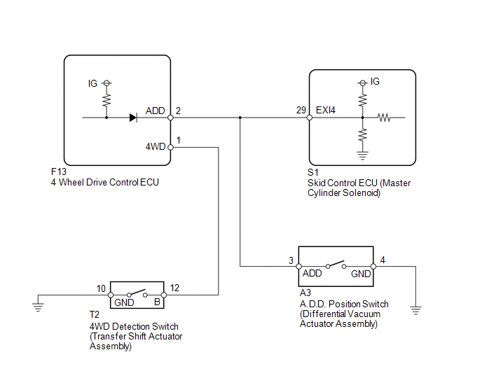
WIRING DIAGRAM
CAUTION / NOTICE / HINT
NOTICE:
When replacing the skid control ECU (master cylinder solenoid), perform calibration
(See page .gif) ).
).
PROCEDURE
|
1. |
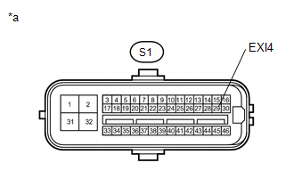
INSPECT SKID CONTROL ECU (EXI4) |
(a) Disconnect the S1 skid control ECU (master cylinder solenoid) connector.
|
(b) Measure the voltage according to the value(s) in the table below. Standard Voltage:
|
|
| NG | .gif) |
GO TO STEP 3 |
|
.gif)
|
2. |
CHECK TEST MODE DTC |
(a) Switch the vehicle to test mode, perform the 4WD detection switch signal
check, and then check that DTC C1282 is cleared (See page
).
|
Result |
Proceed to |
|---|---|
|
DTC is not cleared |
A |
|
DTC is cleared |
B |
| A | |
REPLACE MASTER CYLINDER SOLENOID |
| B | |
USE SIMULATION METHOD TO CHECK |
|
3. |
CHECK HARNESS AND CONNECTOR (SKID CONTROL ECU - 4 WHEEL DRIVE CONTROL ECU AND A.D.D. POSITION SWITCH) |
(a) Disconnect the S1 skid control ECU (master cylinder solenoid) connector.
(b) Disconnect the F13 4 wheel drive control ECU connector.
(c) Disconnect the A3 A.D.D. position switch (differential vacuum actuator assembly) connector.
(d) Measure the resistance according to the value(s) in the table below.
Standard Resistance:
|
Tester Connection |
Condition |
Specified Condition |
|---|---|---|
|
S1-29 (EXI4) - F13-2 (ADD) |
Always |
Below 1 Ω |
|
S1-29 (EXI4) - A3-3 (ADD) |
Always |
Below 1 Ω |
|
S1-29 (EXI4) - Body ground |
Always |
10 kΩ or higher |
| OK | |
GO TO TRANSFER SYSTEM (PROBLEM SYMPTOMS TABLE) |
| NG | |
REPAIR OR REPLACE HARNESS OR CONNECTOR |
 ECM Communication Circuit Malfunction (C1203)
DESCRIPTION
The circuit sends TRAC, A-TRAC and VSC control information from the skid control
ECU (master cylinder solenoid) to the ECM, and engine control information from the
ECM to the skid con ...
 Steering Angle Sensor Zero Point Malfunction (C1290)
DESCRIPTION
The skid control ECU (master cylinder solenoid) acquires steering angle sensor
zero point every time the ignition switch is turned to ON and the vehicle is driven
at 35 km/h (22 mph) ...
Other materials:
Installation
INSTALLATION
CAUTION / NOTICE / HINT
CAUTION:
Be sure to perform this procedure with several people as the transfer assembly
is very heavy.
PROCEDURE
1. INSTALL TRANSFER CASE LOWER PROTECTOR
(a) Install the transfer case lower protector with the 4 bolts.
Torque:
18 N·m {184 kgf·cm, 13 f ...
Data List / Active Test
DATA LIST / ACTIVE TEST
1. DATA LIST
HINT:
Using the Techstream to read the Data List allows the values or states of switches,
sensors, actuators and other items to be read without removing any parts. This non-intrusive
inspection can be very useful because intermittent conditions or signals ...
Slip Indicator Light Remains ON
DESCRIPTION
The slip indicator light blinks during VSC or TRAC and AUTO LSD operation. When
the system fails, the slip indicator light comes on to warn the driver.
WIRING DIAGRAM
CAUTION / NOTICE / HINT
NOTICE:
When replacing the skid control ECU (master cylinder solenoid), perform ...
