Toyota Tacoma (2015-2018) Service Manual: Brake Booster Pump Motor on Time Abnormally Long (C1252)
DESCRIPTION
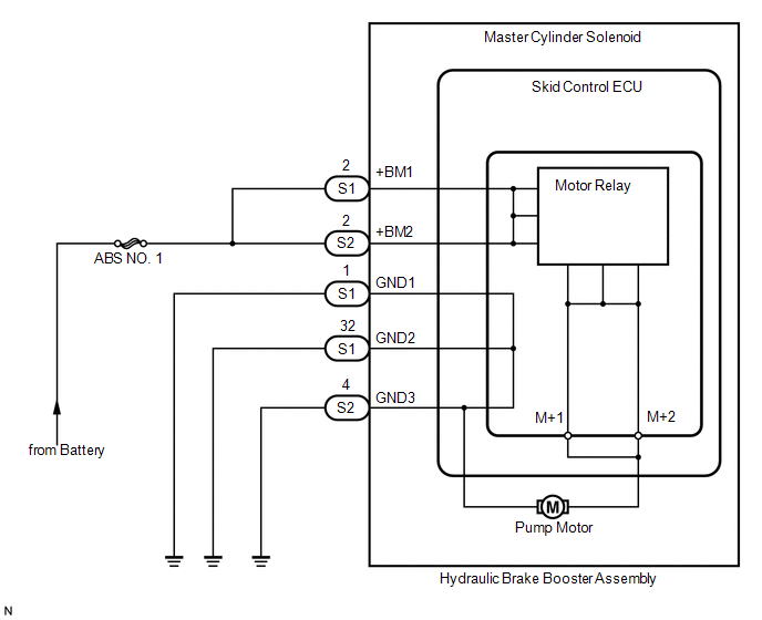
The motor relay (semiconductor relay) is built into the master cylinder solenoid and drives the pump motor based on a signal from the skid control ECU (master cylinder solenoid).
|
DTC No. |
DTC Detecting Condition |
Trouble Areas |
|---|---|---|
|
C1252 |
Motor operates for 5 minutes or more. |
|
WIRING DIAGRAM
CAUTION / NOTICE / HINT
HINT:
When C1253, C1254 or C1256 is output together with C1252, inspect and repair the trouble areas indicated by C1253, C1254 or C1256 first.
PROCEDURE
|
1. |
CHECK HYDRAULIC BRAKE BOOSTER PUMP MOTOR OPERATION |
(a) Turn the ignition switch to OFF.
(b) Depress the brake pedal more than 20 times.
(c) Turn the ignition switch to the ON position.
(d) Check how the hydraulic brake booster pump motor operates.
|
Result |
Proceed to |
|---|---|
|
Pump motor does not operate |
A |
|
Pump motor operates continuously (Does not stop) |
B |
|
Pump motor operates intermittently |
C |
|
Pump motor operates, then stops |
D |
| B | .gif) |
REPLACE HYDRAULIC BRAKE BOOSTER |
| C | |
GO TO STEP 4 |
| D | |
GO TO STEP 5 |
|
.gif)
|
2. |
CHECK BRAKE PUMP MOTOR WIRE HARNESS CONNECTION (MT+ / MT-) |
(a) Using a screwdriver, remove the 2 plugs from the hydraulic brake booster
(See page .gif) ).
).
(b) Check the tightening torque of 2 screws which fasten the wire harness connecting
hydraulic brake booster and brake booster pump (See page
).
Torque:
2.9 N·m {30 kgf·cm, 26 in·lbf}
| NG | |
RETIGHTEN SCREWS |
|
|
3. |
CHECK RESISTANCE OF PUMP MOTOR WIRE HARNESS (MT+/MT-) |
|
(a) Using a screwdriver, remove the 2 screws and pull the wire harness from the hydraulic brake booster assembly. |
|
.png)
(b) Measure the resistance between the red wire (MT+) and black wire (MT-).
Resistance:
2 Ω
| NG | |
REPLACE HYDRAULIC BRAKE BOOSTER |
|
|
4. |
READ VALUE USING DATA LIST (ACCUMULATOR SENSOR) |
(a) Connect Techstream to the DLC3.
(b) Turn the ignition switch to the ON position.
(c) Turn Techstream ON.
(d) Select the Data List mode on the Techstream.
ABS/VSC/TRAC|
Tester Display |
Measurement Item / Range |
Normal Condition |
Diagnostic Note |
|---|---|---|---|
|
Accumulator Sensor |
Accumulator pressure sensor reading / min.: 0 V, max.: 5 V |
3.58 to 5 V |
If value constant regardless of pump operation, accumulator pressure sensor malfunction suspected. |
(e) Check that the accumulator pressure sensor output is normal.
|
Result |
Proceed to |
|---|---|
|
Output value varies within "Normal Condition" range |
A |
|
Output value does not reach "Normal Condition" range |
B |
|
Output value constant regardless of pump motor operation |
C |
| B | |
REPLACE MASTER CYLINDER SOLENOID |
| C | |
REPLACE HYDRAULIC BRAKE BOOSTER |
|
|
5. |
RECONFIRM DTC |
(a) Clear the DTCs (See page
).
(b) Turn the ignition switch to OFF.
(c) Turn the ignition switch to the ON position.
(d) Wait for more than 5 minutes.
(e) Check if the same DTCs are recorded.
|
Result |
Proceed to |
|---|---|
|
DTC output |
A |
|
DTC not output |
B |
| A | |
REPLACE MASTER CYLINDER SOLENOID |
| B | |
REPLACE HYDRAULIC BRAKE BOOSTER |
 Open in Pump Motor Circuit (C1251)
DESCRIPTION
The motor relay (semiconductor relay) is built into the master cylinder solenoid
and drives the pump motor based on a signal from the skid control ECU (master cylinder
solenoid).
...
 Pump Motor Relay (C1253)
DESCRIPTION
The motor relay (semiconductor relay) is built into the master cylinder solenoid
and drives the pump motor based on a signal from the skid control ECU (master cylinder
solenoid).
...
Other materials:
Rear Right Center Sensor Malfunction (C1AE8)
DESCRIPTION
The No. 1 ultrasonic sensor (rear center sensor RH) is installed on the rear
bumper. The ECU detects obstacles based on signals received from the No. 1 ultrasonic
sensor (rear center sensor RH). If the No. 1 ultrasonic sensor (rear center sensor
RH) has an open circuit or other ma ...
On-vehicle Inspection
ON-VEHICLE INSPECTION
PROCEDURE
1. INSPECT COOLER CONDENSER ASSEMBLY
(a) If the fins of the cooler condenser assembly are dirty, clean them with water
and dry them with compressed air.
NOTICE:
Do not damage the fins of the condenser assembly.
(b) If the fins of the cooler condenser assembly ...
Components
COMPONENTS
ILLUSTRATION
ILLUSTRATION
ILLUSTRATION
ILLUSTRATION
...
