Toyota Tacoma (2015-2018) Service Manual: Brake
General Maintenance
GENERAL MAINTENANCE
PROCEDURE
1. INSPECT BRAKE LINE PIPES AND HOSES
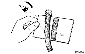
HINT:
Work in a well-lighted area. Turn the front wheels fully to the right or left before beginning.
(a) Check all the brake lines and hoses for:
- Damage
- Wear
- Deformation
- Cracks
- Corrosion
- Leaks
- Bends
- Twists
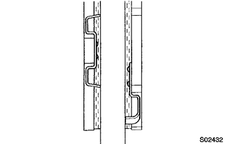
(b) Check all the clamps for tightness and the connections for leakage.
(c) Check if the hoses and lines are not near sharp edges, moving parts and the exhaust system.
(d) Check if the lines are installed pass through the center of the grommets.
2. INSPECT FRONT BRAKE PADS AND DISCS
HINT:
- (See page
.gif) )
) - If a squealing or scraping noise is heard from the brake while driving, check the pad wear indicator.
- If there are traces of the indicator contacting the disc rotor, the disc pad should be replaced.
3. INSPECT REAR BRAKE DRUM
HINT:
See page
4. INSPECT BRAKE FLUID
Fluid:
SAE J1703 or FMVSS No. 116 DOT3
HINT:
- for Hydraulic Brake Booster (See page
)
- for Vacuum Brake Booster (See page )
 Body
Body
General Maintenance
GENERAL MAINTENANCE
PROCEDURE
1. TIGHTEN BOLTS AND NUTS ON CHASSIS AND BODY
(a) Tighten the bolts and nuts on the chassis parts listed below, if necessary.
Front axle ...
 Chassis
General Maintenance
GENERAL MAINTENANCE
PROCEDURE
1. INSPECT STEERING LINKAGE
(a) Check the steering wheel free play (See page
).
(b) Check the steering linkage for looseness or damage.
(1) ...
Other materials:
Air Conditioning Amplifier
Components
COMPONENTS
ILLUSTRATION
Installation
INSTALLATION
PROCEDURE
1. INSTALL AIR CONDITIONING AMPLIFIER ASSEMBLY
(a) Install the air conditioner amplifier assembly with the 2 bolts.
Torque:
7.0 N·m {71 kgf·cm, 62 in·lbf}
(b) Connect the 2 connectors.
2. INSTALL INSTRUMENT L ...
Terminals Of Ecu
TERMINALS OF ECU
1. CHECK COMBINATION METER ASSEMBLY
(a) Measure the resistance and voltage according to the value(s) in the table
below.
Terminal No. (Symbol)
Wiring Color
Terminal Description
Condition
Specified Condition
...
Child restraint systems
A child restraint system for a small child or baby must itself be properly
restrained on the seat with the lap portion of the lap/shoulder belt.
The laws of all 50 states of the U.S.A. and Canada now require the use of child
restraint systems.
Points to remember
Studies have shown that instal ...
